RSL 3
Gallery B
- Photo Sources:
- 7nnn: Historic American Engineering Record: SRMSC
RSL 3 Gallery B
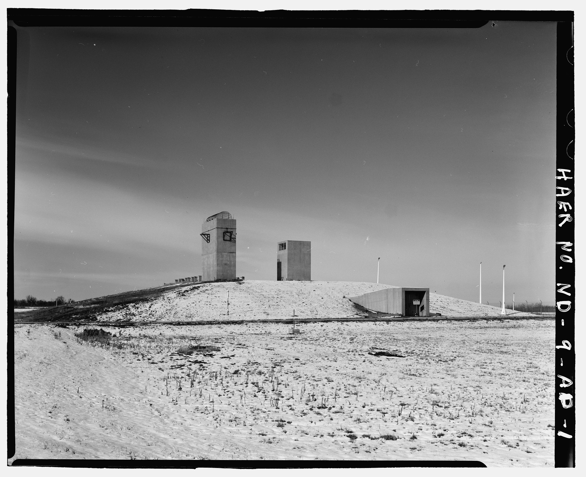
- Located northeast of the MSR (near the PAR).
- 16 Sprint launchers.


-
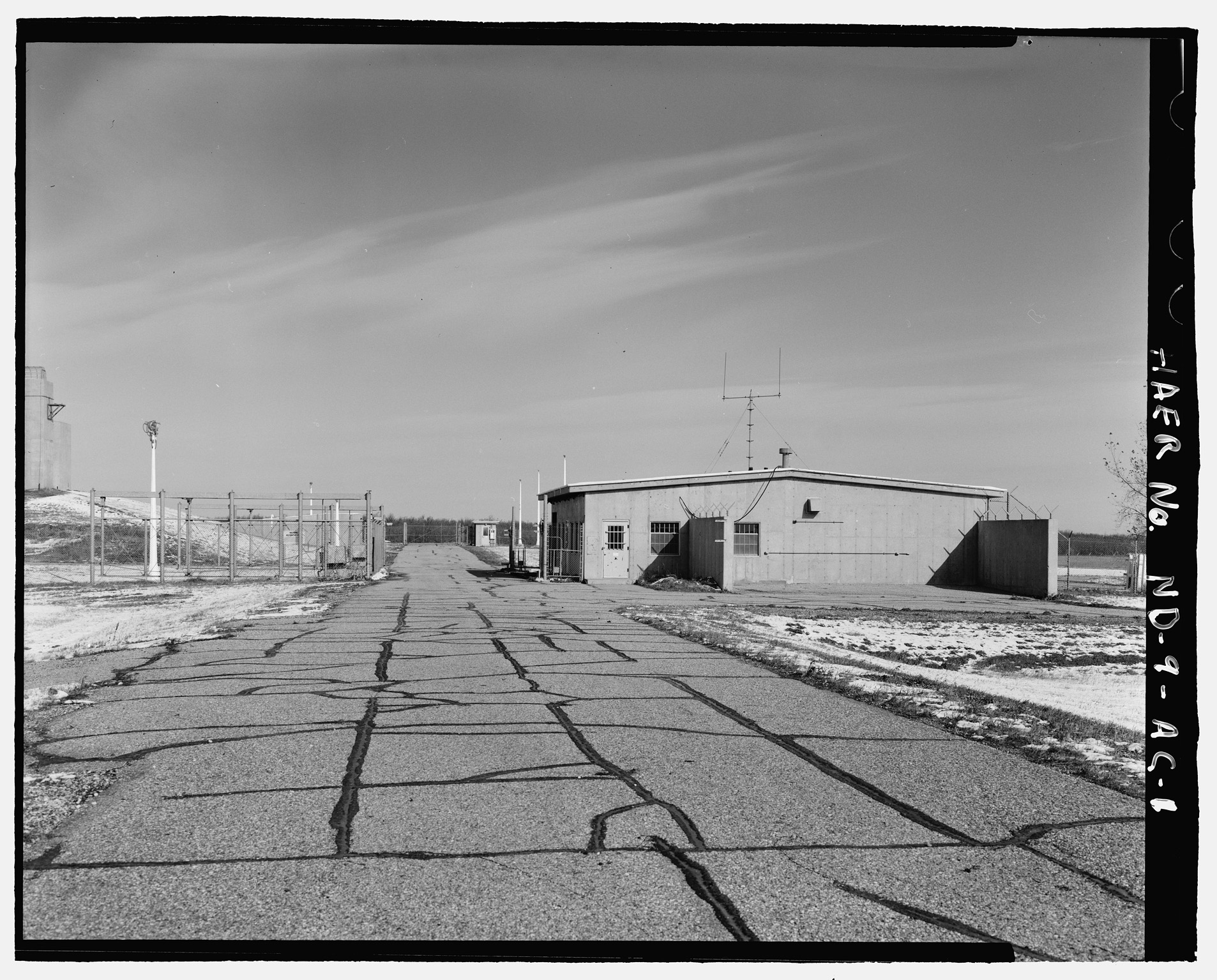
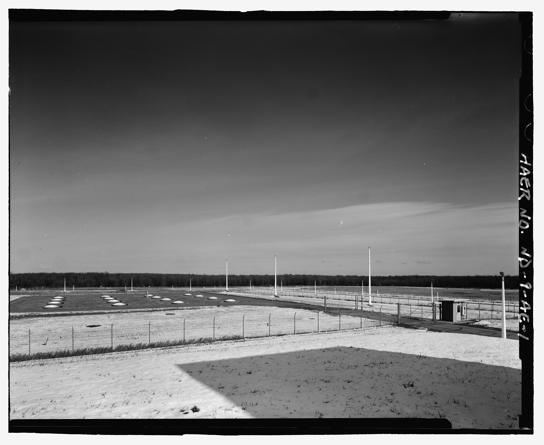
7480: View from just inside the entrance gate.
- Left: RLOB.
- Right: LASS.
- 7481: LASS with sally port at left.
- 7482: RLOB.


-
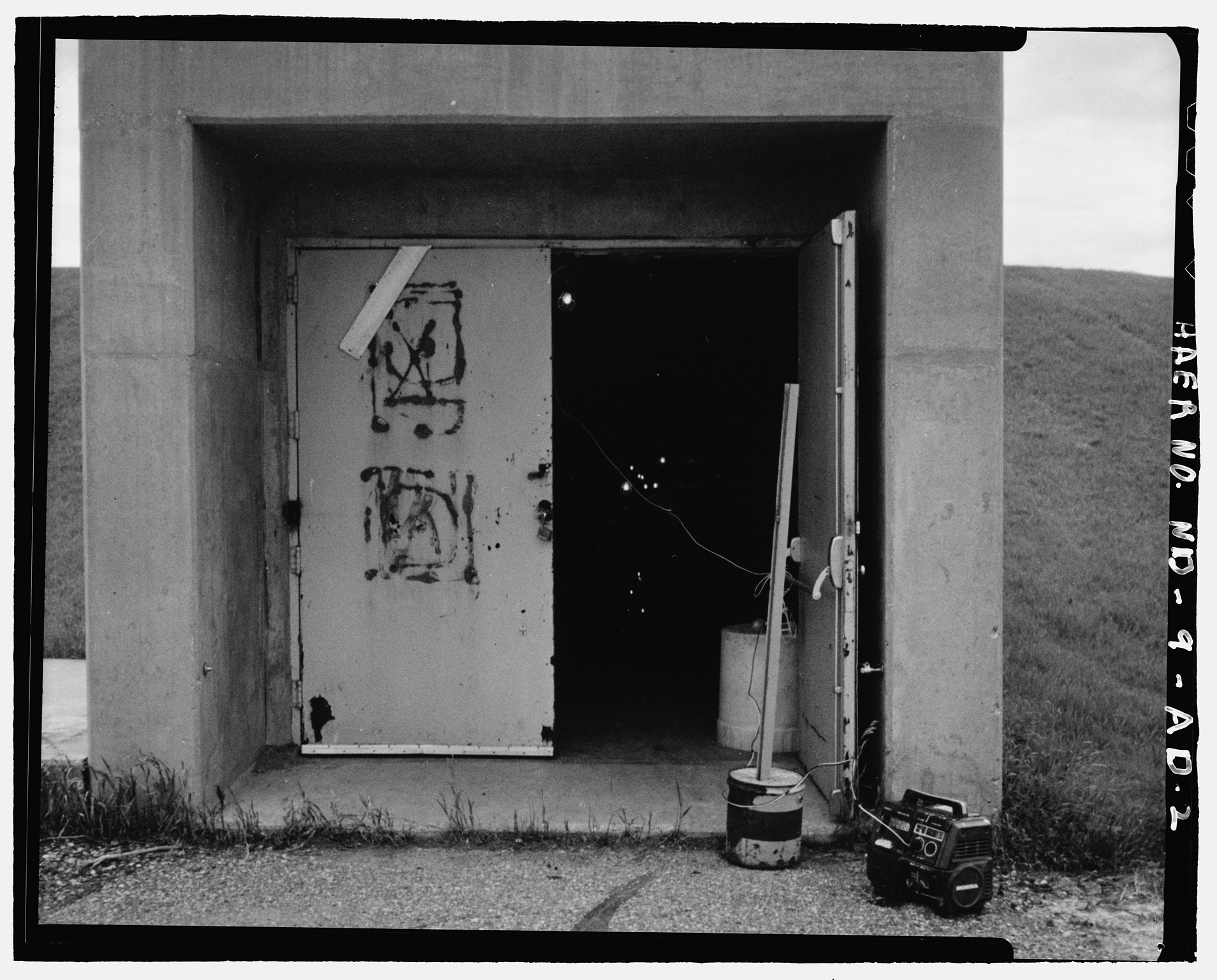
7483: Tunnel entrance leading into RLOB.
- Photo by Gerald Greenwood, June 1993.
-
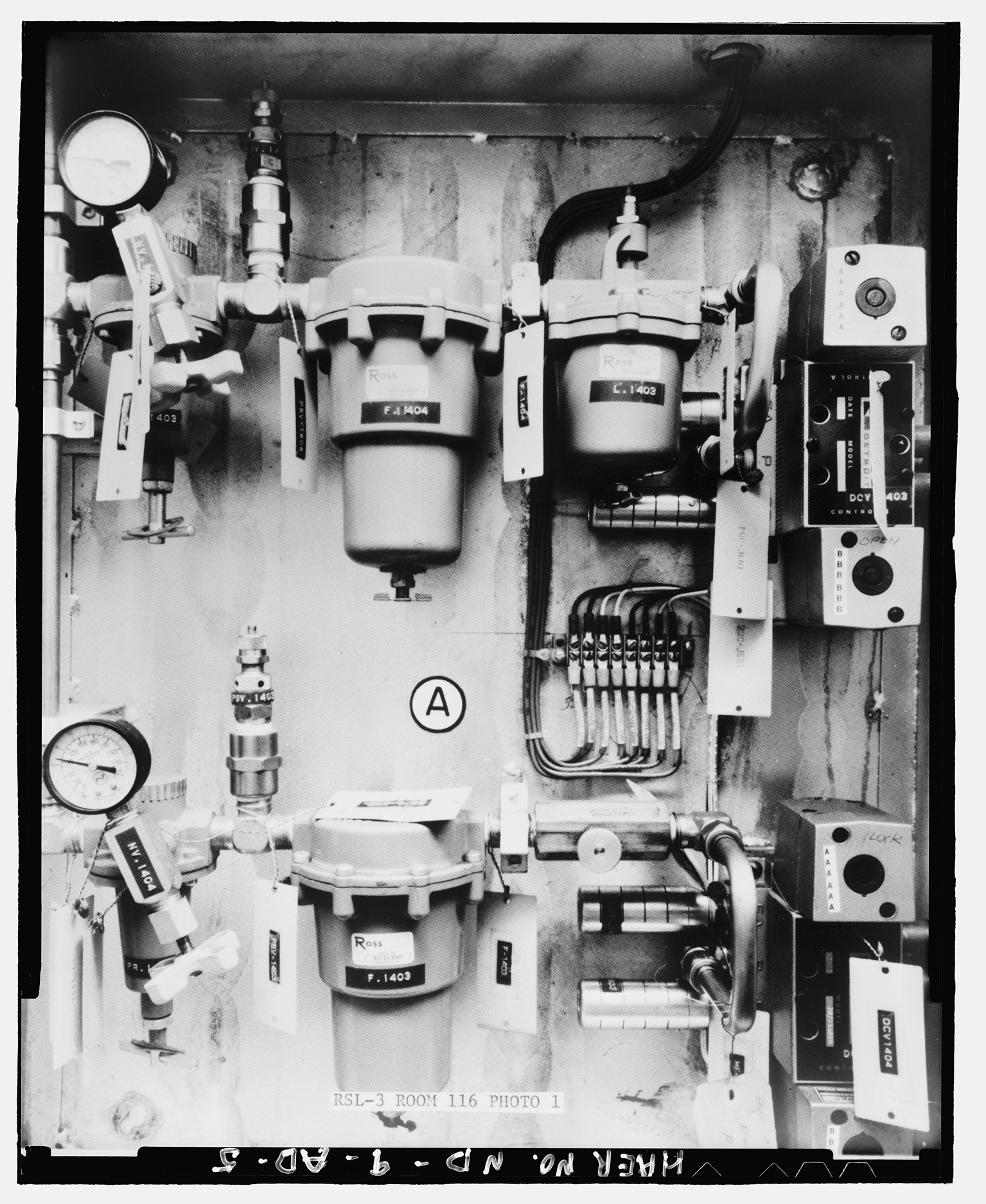
7486: View of pneumatic control panel regulating entrance to waiting room #116.
- The panel activated the pneumatic cylinder for opening and closing of blast doors #116 and #118.
- A rotary air motor actuated locking and unlocking of the doors.
- Photographer unknown, 1 September 1974.
-
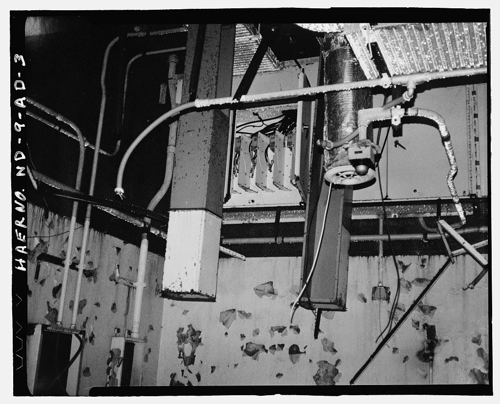
7484: Interior of remote launch operations building, room unknown, demonstrating the result of salvaging operations.
- Note the ceiling tiles have been removed.
- Photo by Gerald Greenwood, June 1993.

-
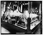
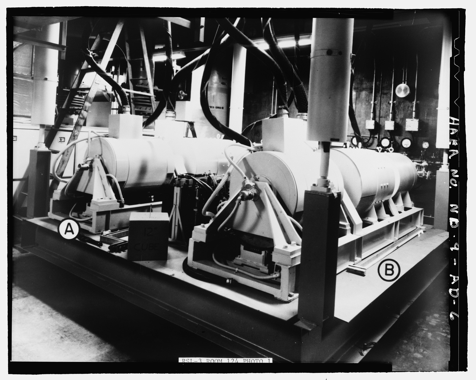
7487: View of remote launch operations building, power generation room #124, showing no-break units NB-1002 (A) and NB-1001 (B).
- This equipment consisted of a 150 horsepower, D.C. operational motor which drove, on each end of the extended shaft, a 70 kw generator and a 30 kw generator unit.
- It was designed to provide continuous power service for launch equipment.
- Photographer unknown, 1 September 1974.
-
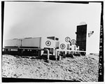
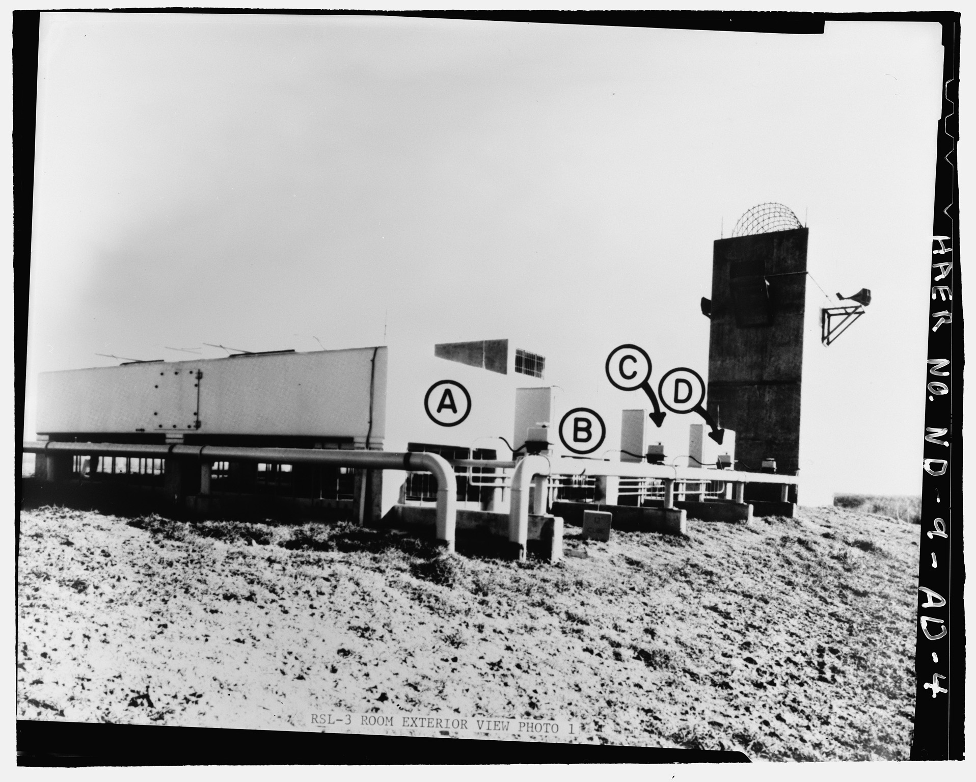
7485: View of remote launch operations building exterior (southwest corner), prior to earth mounding.
- A,B,C, and D are heat exchangers HX-1102B, HX-1102A, HX-1101B, and HX-1101 A, respectively.
- The heat exchangers transferred heat from the cooling water to the outside air during the normal operating mode.
- On the far right is the air exhaust shaft.
- Photographer unknown, 1 September 1974.
- 7491: EASS (right) and launch area (left).

-
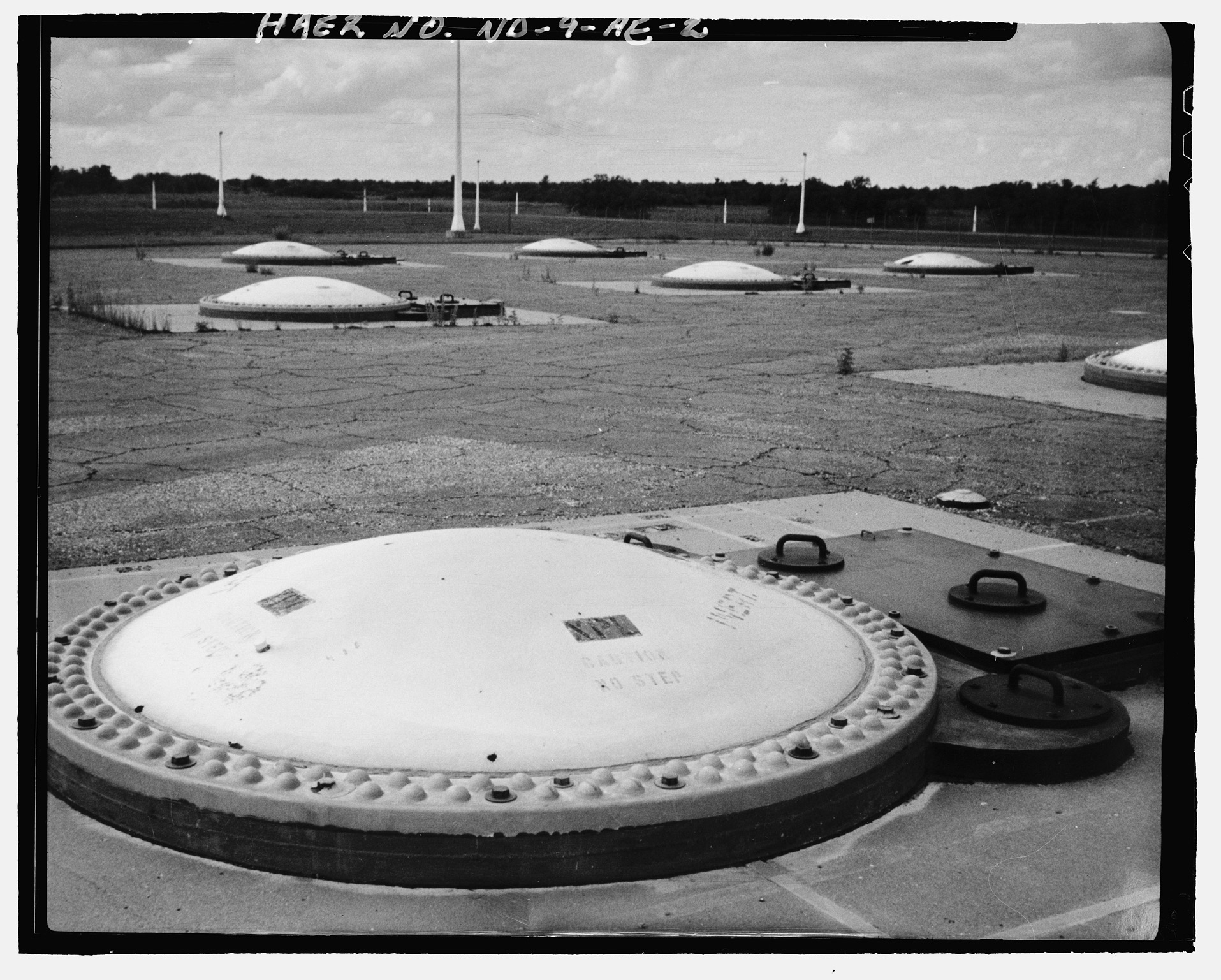
7492: Sprint launch cell.
- Cover was marked "INERT" after site deactivation.
- Photo by Gerald Greenwood, June 1993.