Site Index, Search, Glossary. Updated 10 July 2021, flagged by <$
Home > System Components > PAR Complex >
Safeguard PAR | USAF PARCS >
PAR Complex Photo Galleries > PAR Power Plant
PAR Power Plant
-
Photo Sources:
-
7nnn: Historic American Engineering Record: SRMSC
-
Lnnn: Cynthia LaNell via Facebook (2)
-
Tnnn: 10SWS Facebook page
PAR Power Plant
-
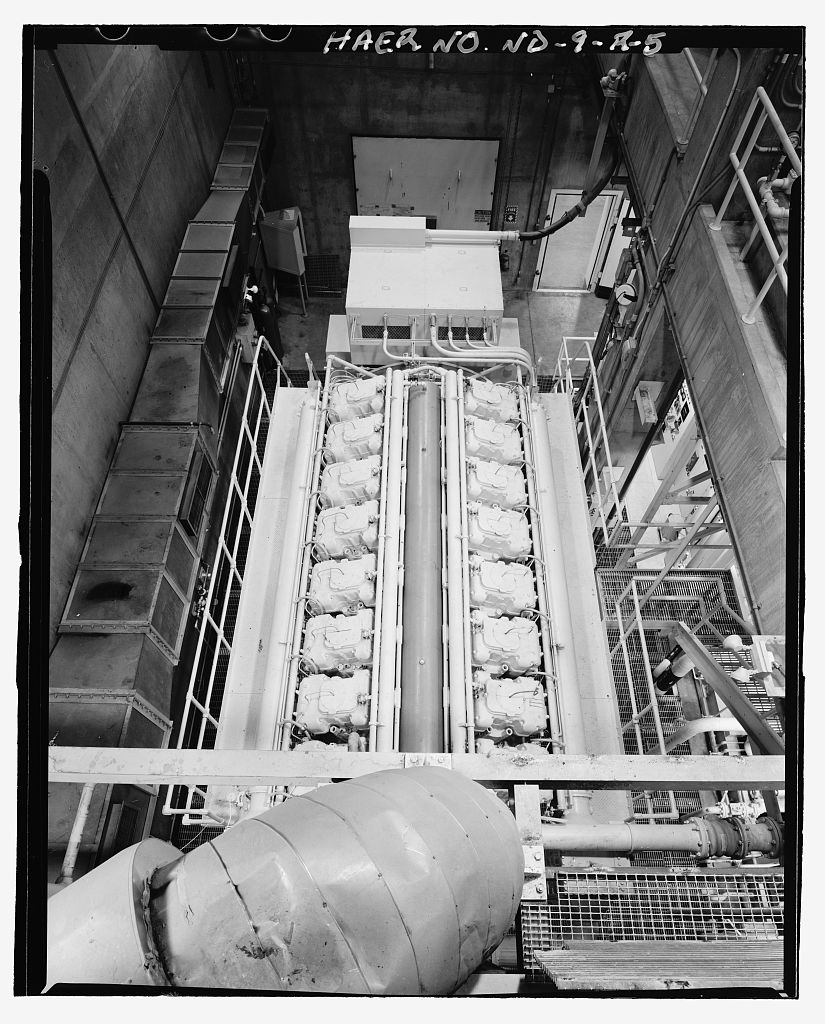
The five generators could produce 14.3 megawatts and were powered by 16 cylinder diesel engines.
-
Power Plant Comments <$
-
Power Plant Videos <$
-
While not the actual PAR/MSR power plant, these two videos show the Cooper-Bessemer LSV-16 prime mover driving a generator. This is the same engine used in the PAR and MSR power plants.
-
Cooper Bessemer LSV16 4000kw Diesel Generator - Walk Around
YouTube 1:46, 21 Mar 2018 (New Window)
-
Cooper Bessemer LSV16 4000kw Diesel Generator - Catwalk Walk Around
YouTube 1:50, 21 Mar 2018 (New Window)
-
Posted by Michael Ophus via Facebook (2)

(opens in new window)
-
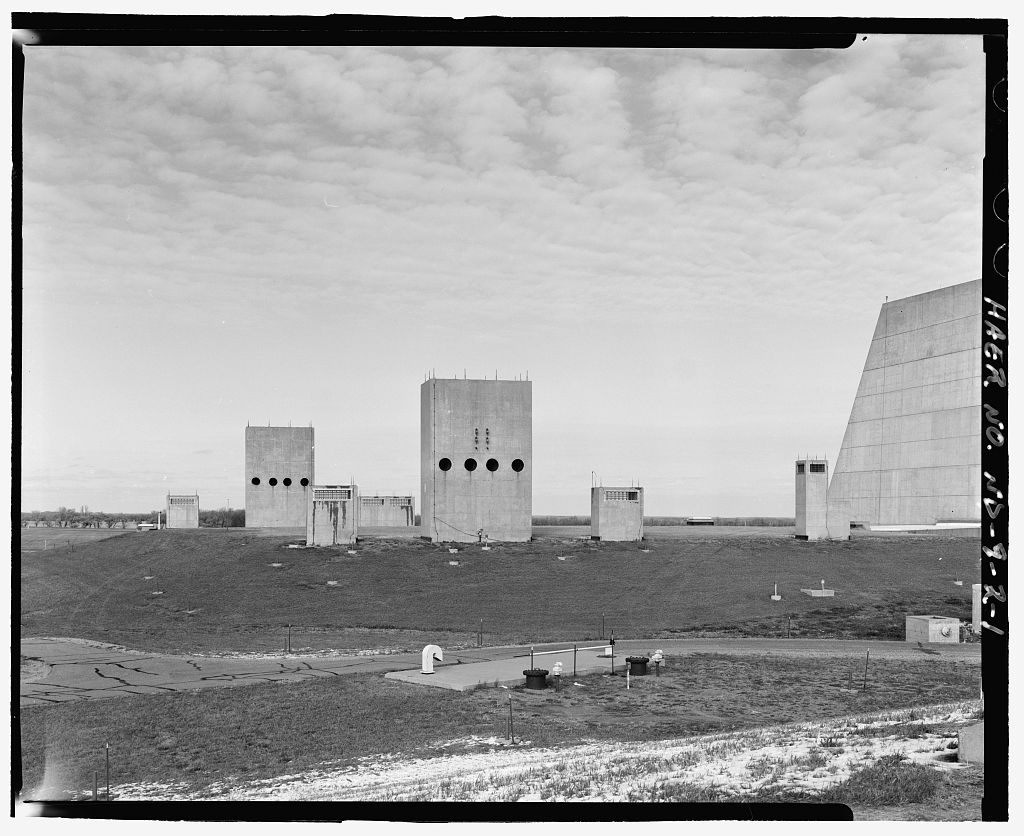
7453: Diesel exhaust (large) and intake (small) stacks.
-
On the right is the ventilating air intake/exhaust, distinguishable by its square shape, whereas the diesel columns are rectangular.
-
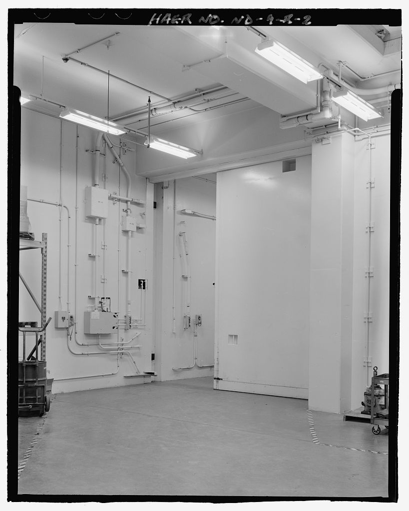
7400: Accessway #101 leading into par power plant from service road B in foreground.
-
7454: Accessway 101, showing equipment blast lock #102.
-
Entrance for fire trucks and equipment.
-
An underground structure at its origin, the 177-foot long accessway is above ground at its south end, terminating in the parking lot of service road B (see 7400).
-
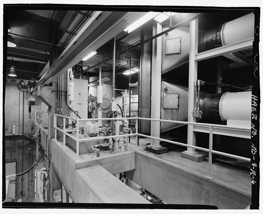
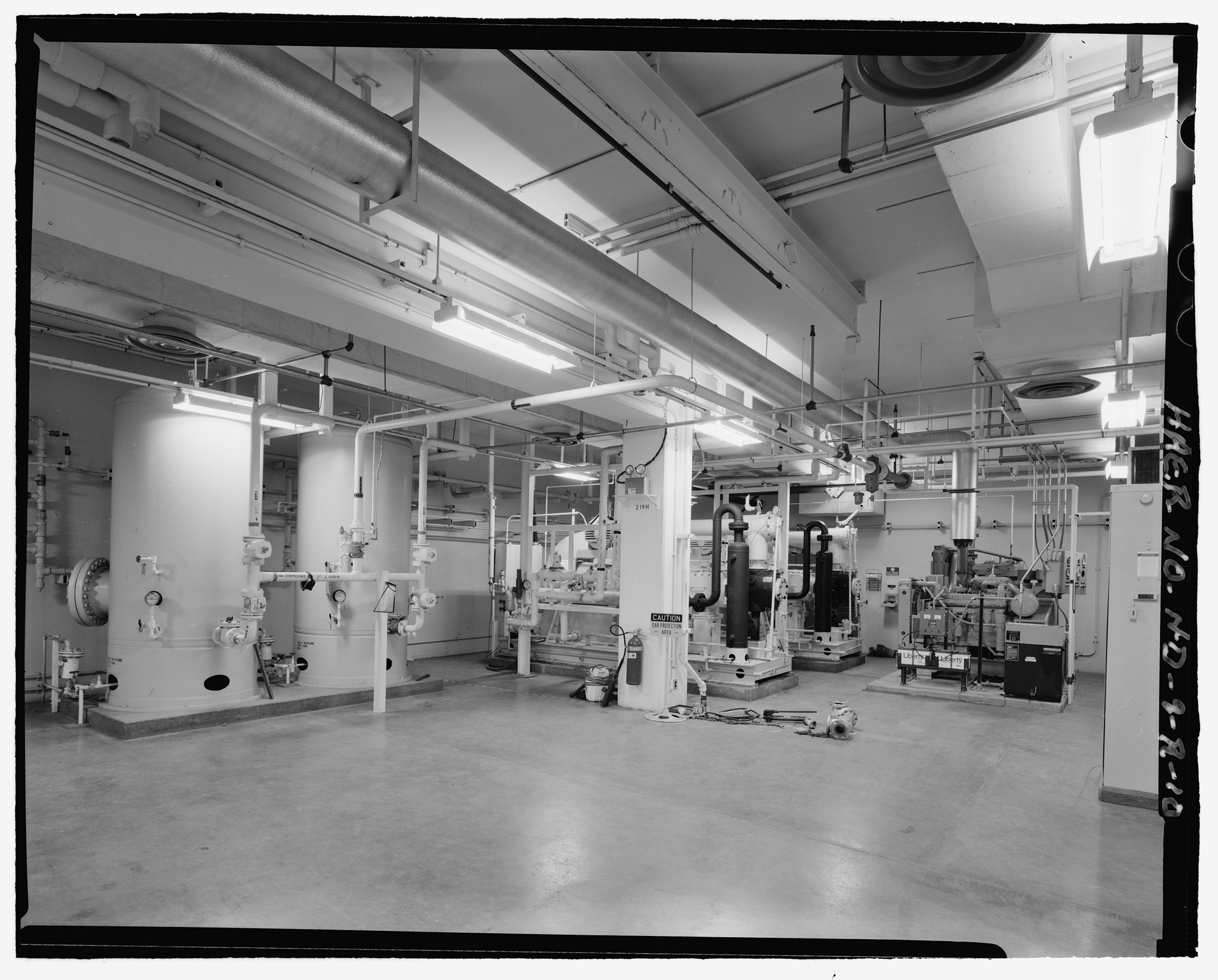
7462: Station services room (upper level); .
-
Shows air compressors which provide diesel generators with internal power kick-on.
-
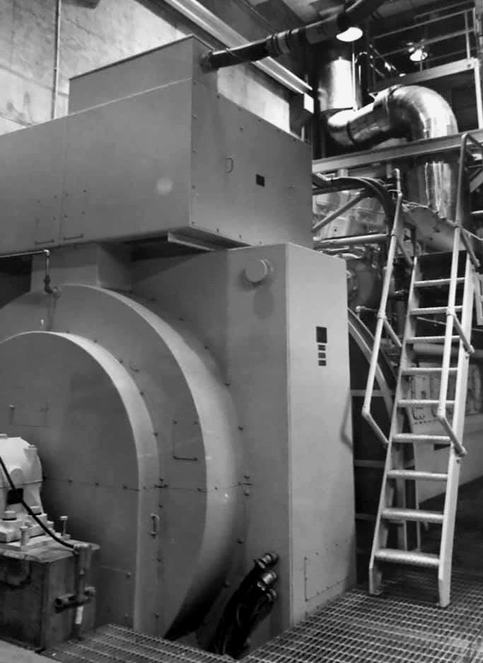
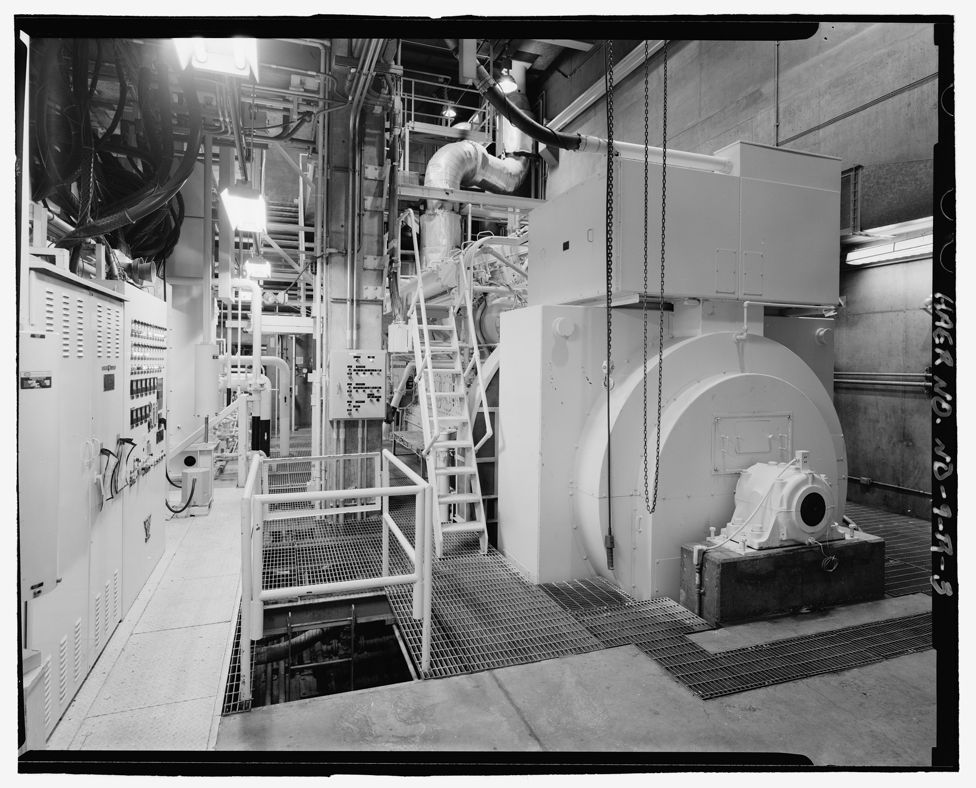
7455: Generator M1, lower level, view from doorway.
-
From David McKinney Jr via Facebook (2) <$
Looking at the flywheel and generator set as well as the catwalk ladder to access the top of the engine. Another staircase led to the bottom of the engine to clean up oil, which always made its way out of the oil pan.
-
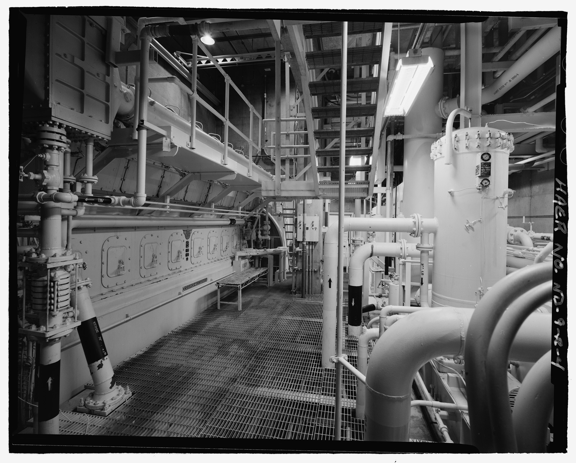
7456: Generator M1, view from rear of room, showing fuel tanks.
-
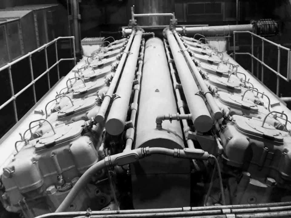
7457: Generator M1, view from above and rear of room (facing corridor doorway).
-
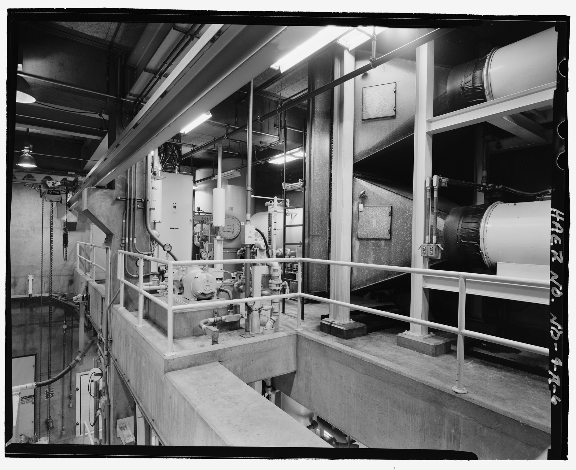
7458: Generator M1, air intakes.
-
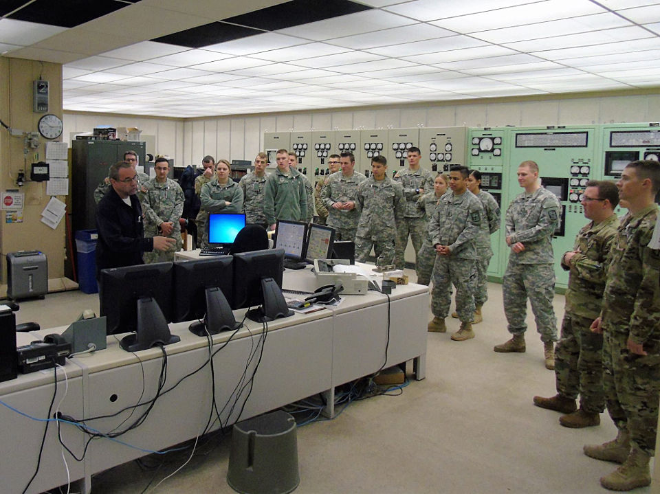
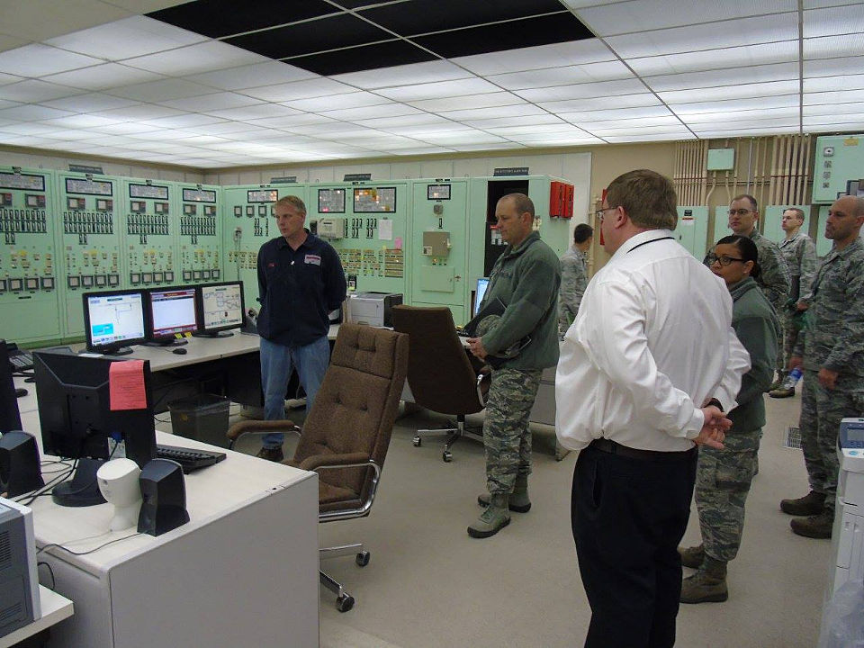
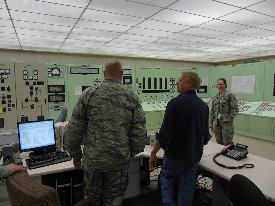
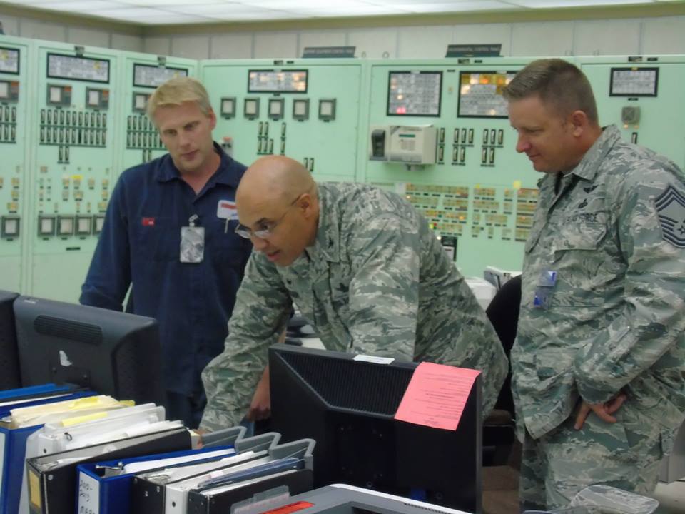
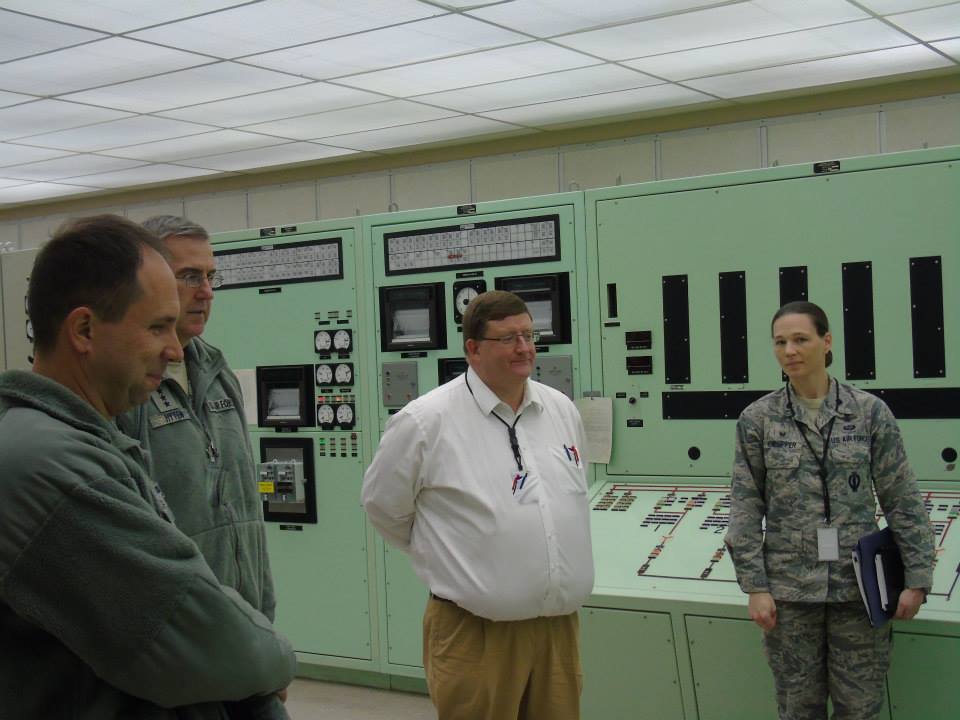
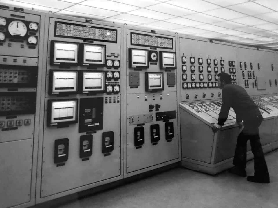
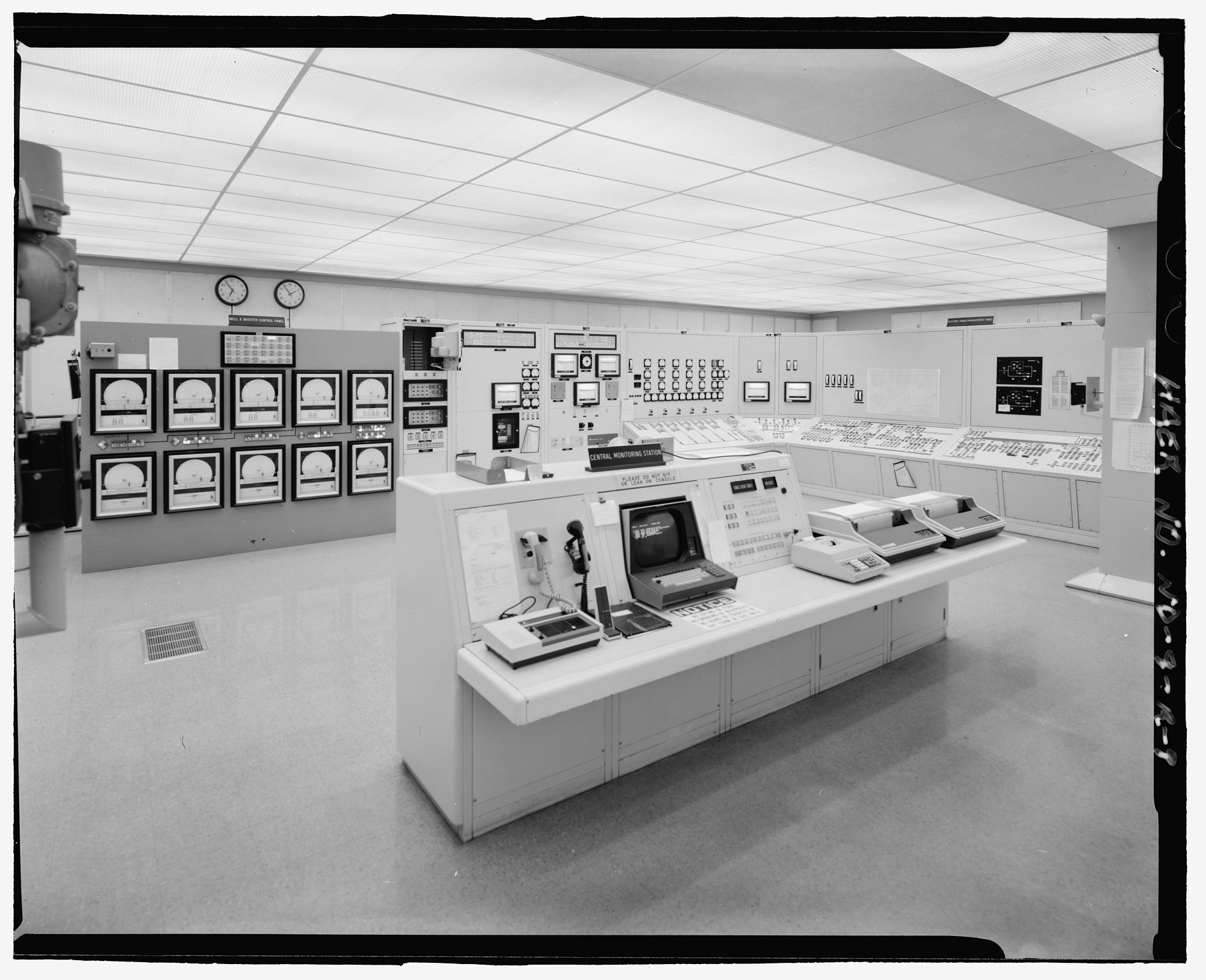
7461: Control room; showing central monitoring station console in foreground.
-
Well and booster control panel in left background and electric power management panel on far right.
-
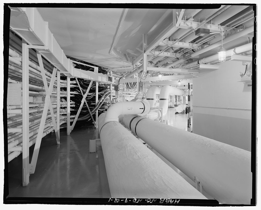
7451: Utility tunnel.
-
View facing into PARB.
-
This tunnel connects the PARB with its power plant.
-
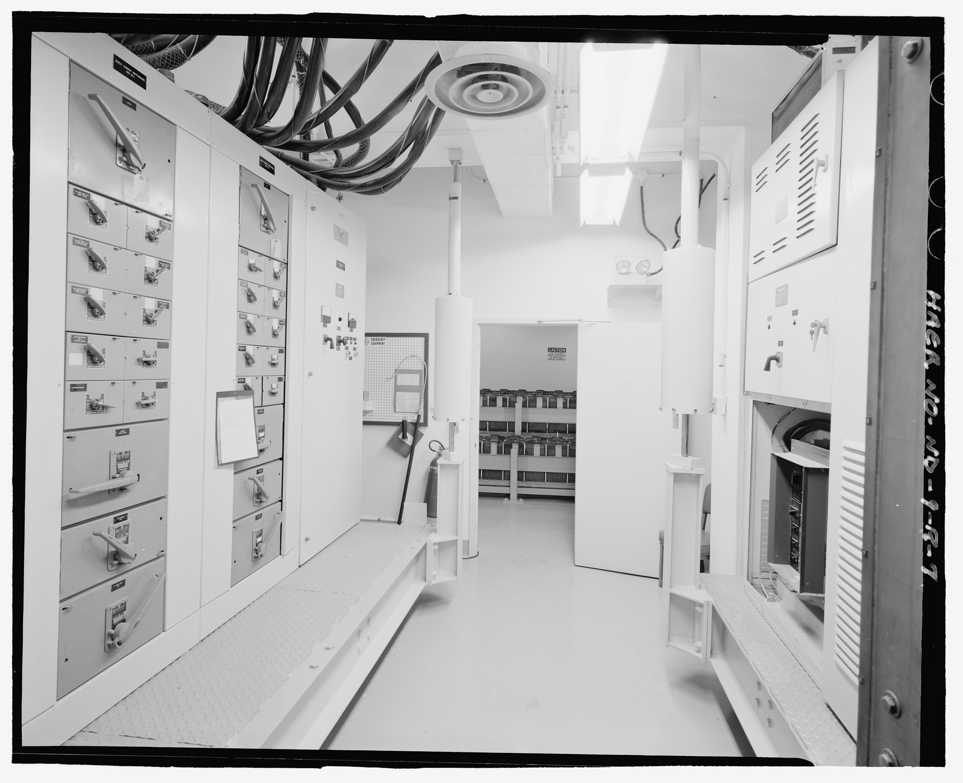
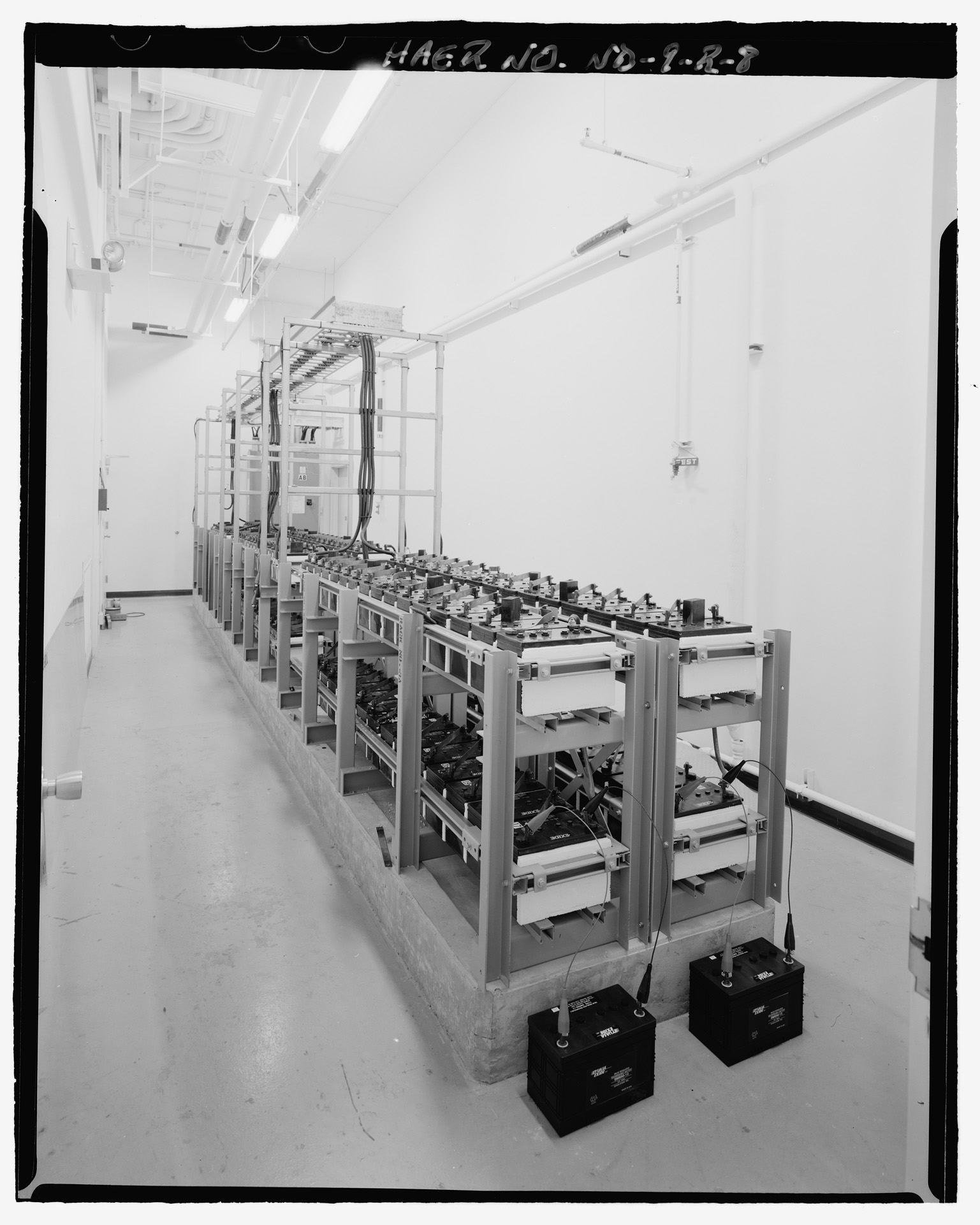
7459: Battery equipment room.
-
Battery room (in background).
-
Multiple source power converter (in foreground).
-
Photo offers another look at the shock-isolation system developed for each platform.
-
7460: Battery room; showing battery racks.
-
The dc power of these batteries is distributed to motor-control centers, the annunciator system, and fire alarm and tripping circuits.
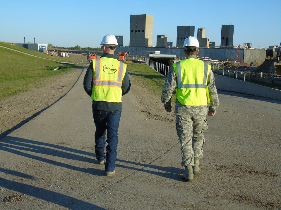
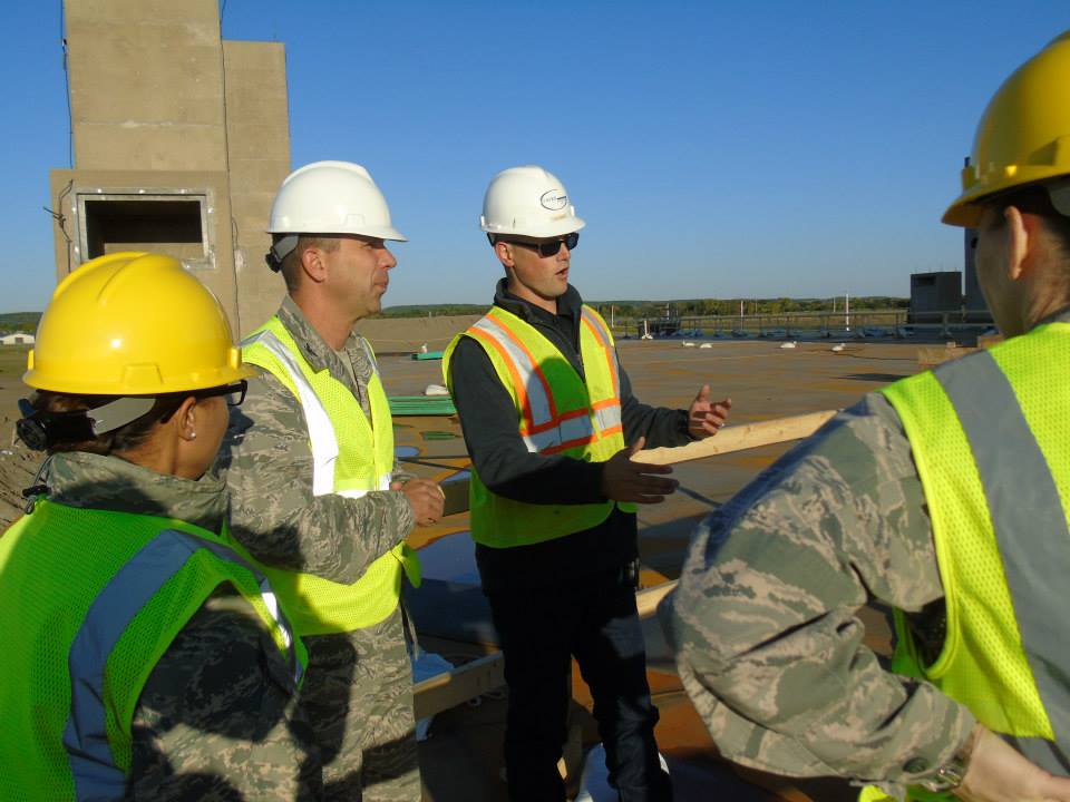
Power Plant Upgrade (2014)
-
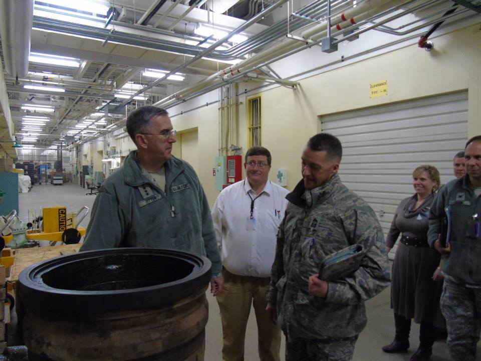
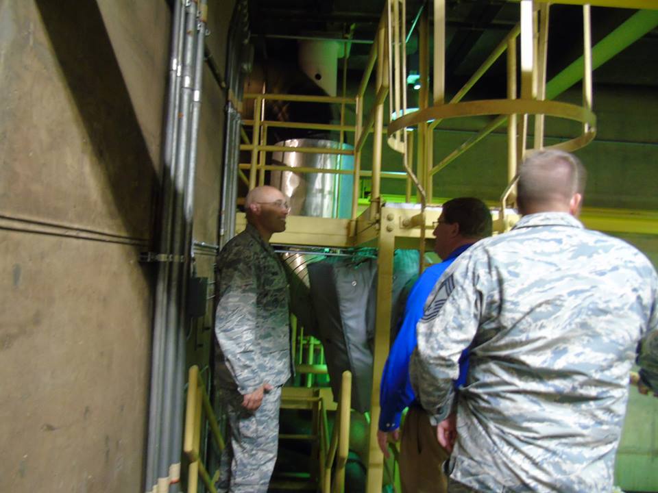
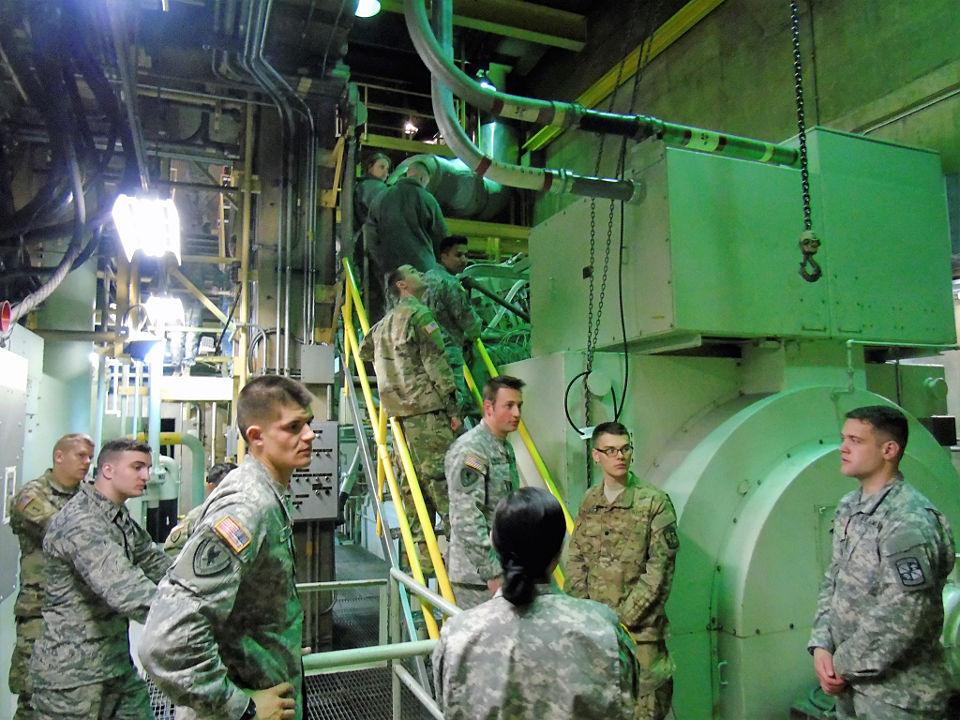
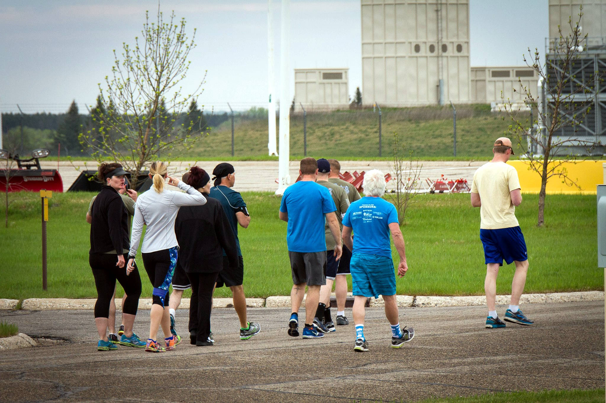
T049: 2017 police week photo showing new power plant stacks.


