MSR / MSCB Photos: Interior
Antenna Beam Steering
- Information on this page from:
-
Stanley R Mickelsen Safeguard Complex Virtual Tour (new window)) -
ABM R & D at Bell Labs: Chapter 7, Missile Site Radar -
Antenna Installation photo gallery
Phased Array Antennas (YouTube, new window)).
The beam steering computer (BSC) received beam direction commands from the data processing system (DPS) and computed the orders for each bit in each of the 5000 phase shifters per array.
The computed orders were then processed by drive-amplifier cards contained within the DDA's.
(No photo available)
The computed orders were then processed by drive-amplifier cards contained within the DDA's.
(No photo available)
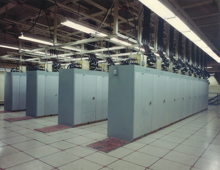
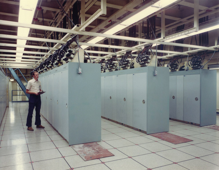
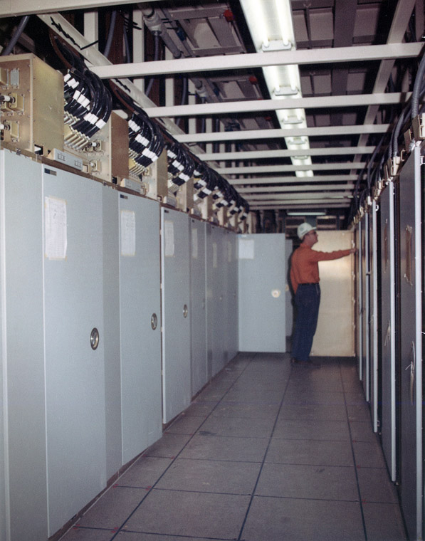
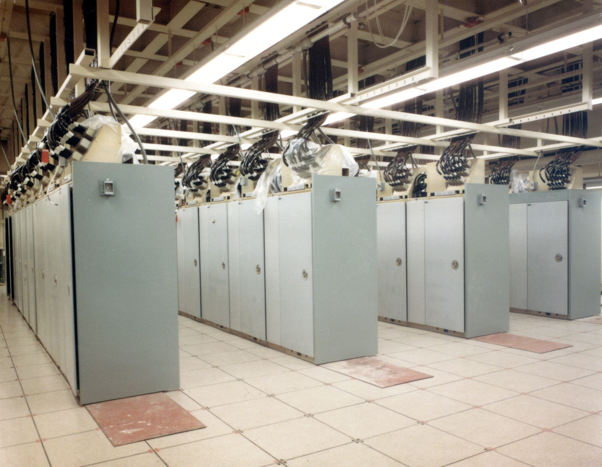
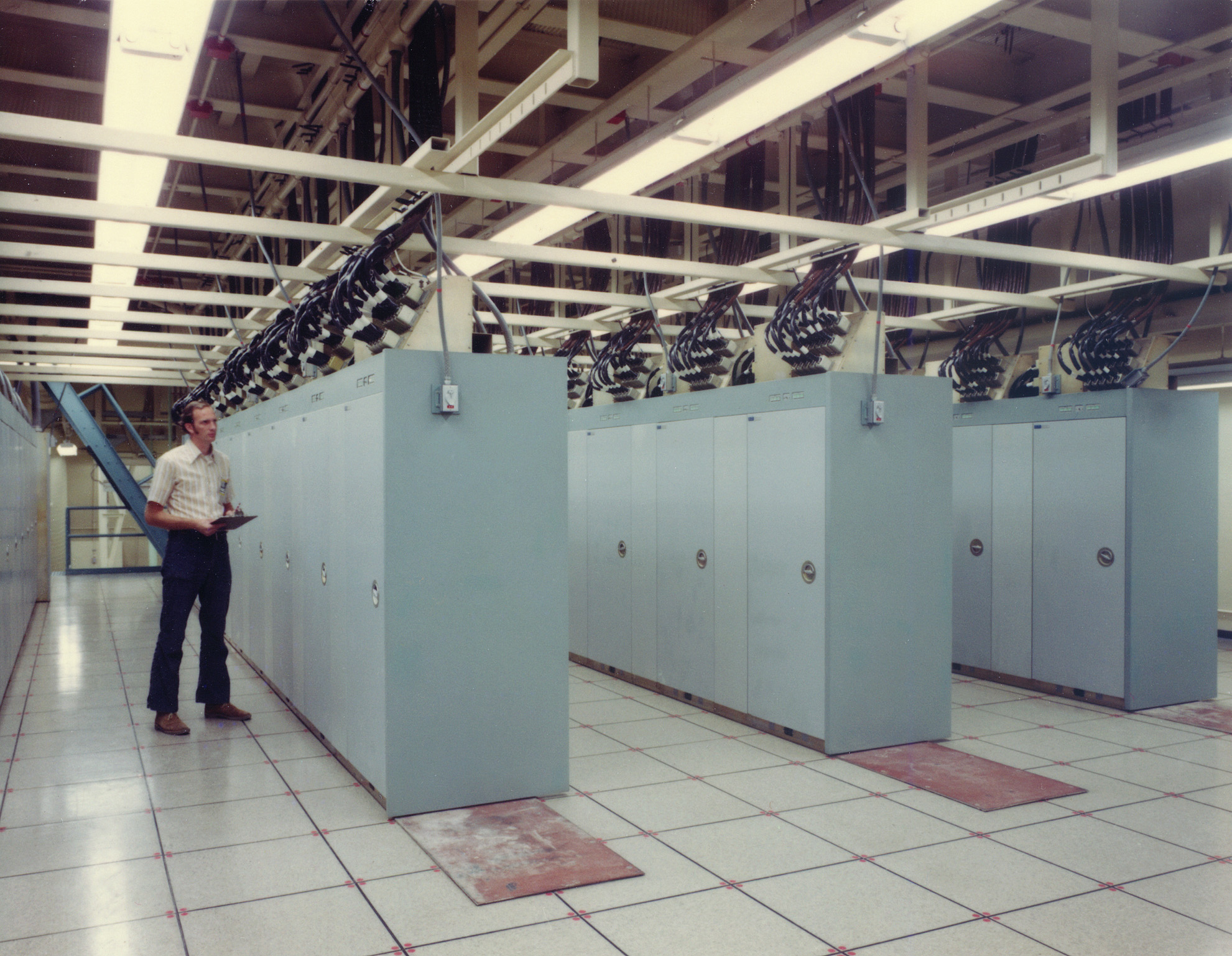
The digital data amplifiers (DDA's) were located on level 3 of the MSCB. There were four rows of DDA's, one for each antenna face. Each row contained 5,000 drive-amplifier cards, one for each antenna element (phase shifter).
The drive-amplifier cards processed the 4 bit words computed by the BSC to generate the forward and reverse bias for the phase shifter diodes to provide electronic beam steering.
The drive-amplifier cards processed the 4 bit words computed by the BSC to generate the forward and reverse bias for the phase shifter diodes to provide electronic beam steering.

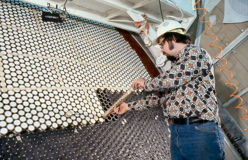
The phase shifter cartridge (antenna element or delay line) altered the phase of the element's radiated energy in order to steer the antenna beam.
The outside of each element was covered by a beryllia window.
The outside of each element was covered by a beryllia window.