Site Index, Search, Glossary
Home > Miscellaneous > Reunion > Reunion Merchandise >
Photo CD Samples
SRMSC Photo CD - Sample Content
General Information
-
(Contributors Name) is in italics following description.
-
The CD contains:
-
496 photos of the Mickelsen Complex, most take back when the site was operational. Most photos are available in two sizes:
-
Medium - click thumbnail or (M)
-
Large - click (L)
-
If your browser automatically re-sizes images to fit the window, you'll need to click on the "large" photos after they are displayed to see all the detail.
-
a 1974 site telephone directory (pdf)
-
everything you ever wanted to know about the MSR transmitter
-
memories and stories from those who submitted the photos
-
plus lots more.....
MSR Complex Samples
-
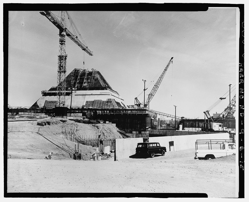
7348: MSCB and power plant under construction (HAER).
-
7334: MSCB turret, northeast face (HAER).
-
At the lower right is open blast door #BD2.
-
This emergency escape, at stair no. 12, is NEMP/RFI-shielded and 16" thick.
-
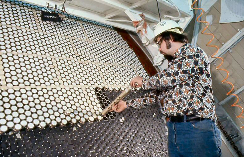
1021: Installation of an antenna element (delay line) (Ves Fulp).
-
Each of the four antenna faces contained 5,000 of these elements.
-
Under computer control, the delay line altered the phase of the element's radiated energy in order to steer the antenna beam.
-
The outside of each element was covered by a beryllia window.
-
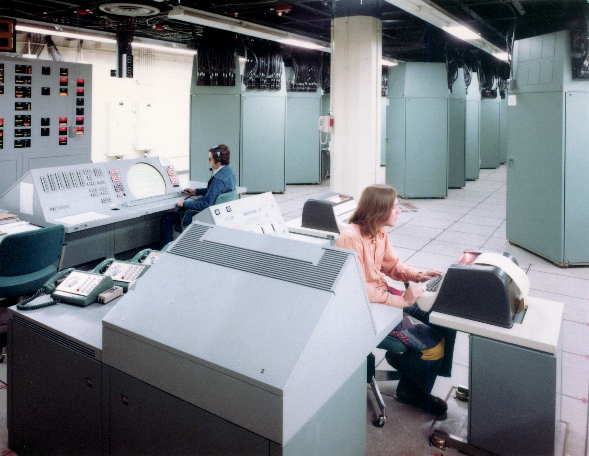
0065: Data processing system (Anonymous WECo engineer).
-
Consoles (foreground), digital racks (background).
-
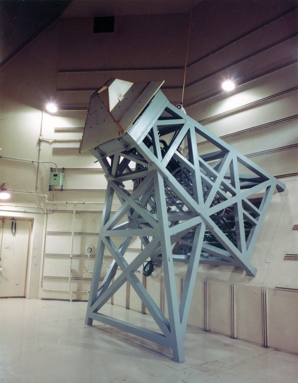
0016: Anechoic chamber, antenna feedhorn assembly (Anonymous WECo engineer).
-
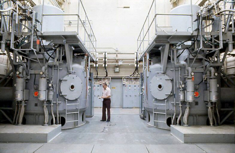
1069: Klystron room.
-
Each of the two klystrons is mounted in a tank containing 3,500 gallons of high dielectric strength transformer oil.
-
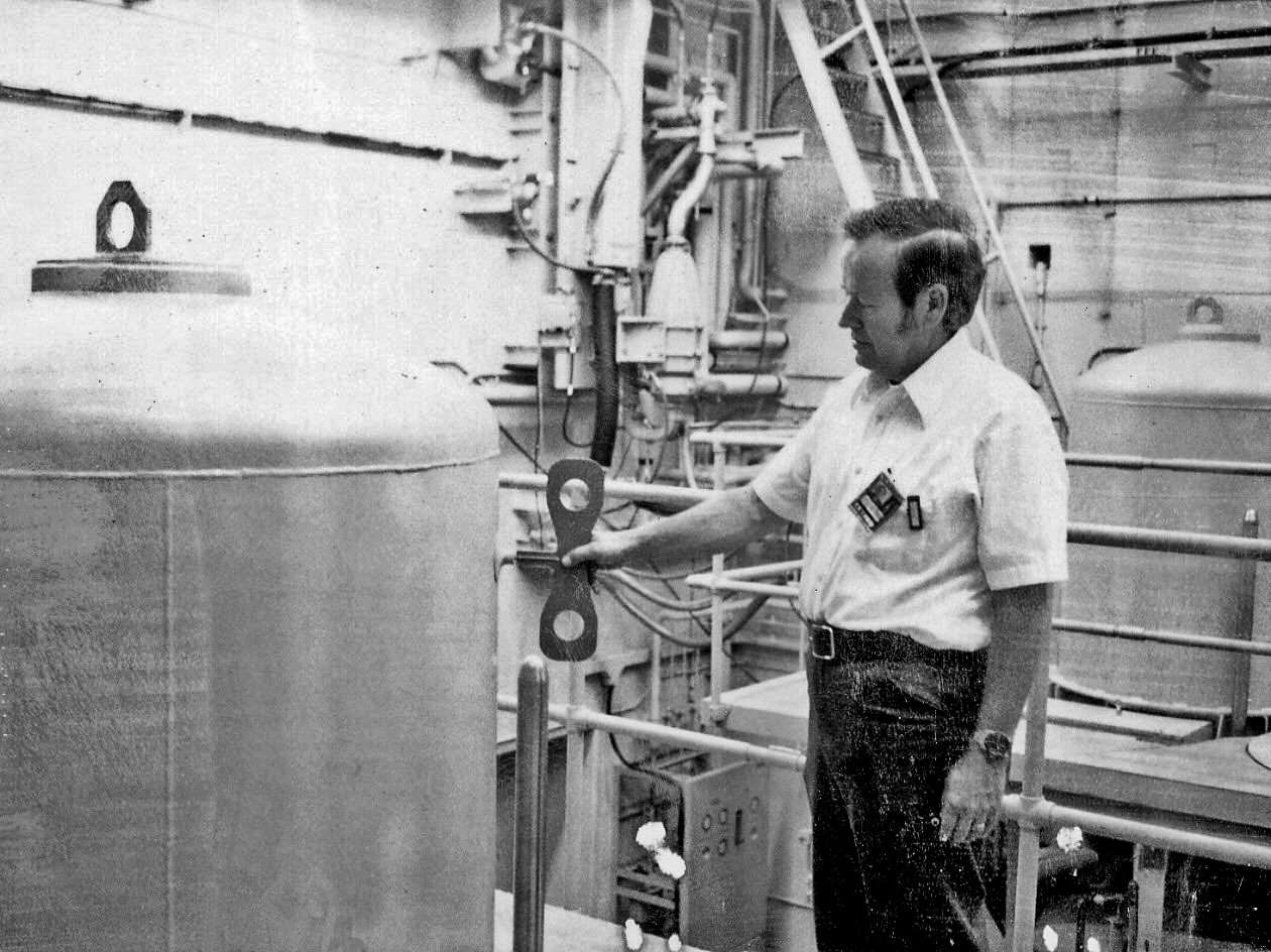
1037: Ves Fulp winds up one of the klystron hats (Ves Fulp).
-
"That was done as a joke. Our ancillary guy comes in one morning and brought that thing, it's a toy, and said we've gotta get a picture of that. I think that was a polaroid picture. That is the klystron hat on the left, that thing weighs about 6,000 pounds. It's 3/4 inch lead with a 1/4 inch stainles steel liner. I'm standing on one platform and you can see one on the other side."
-
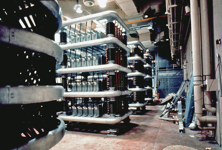
1066: High voltage room, capacitor banks (Ves Fulp).
-
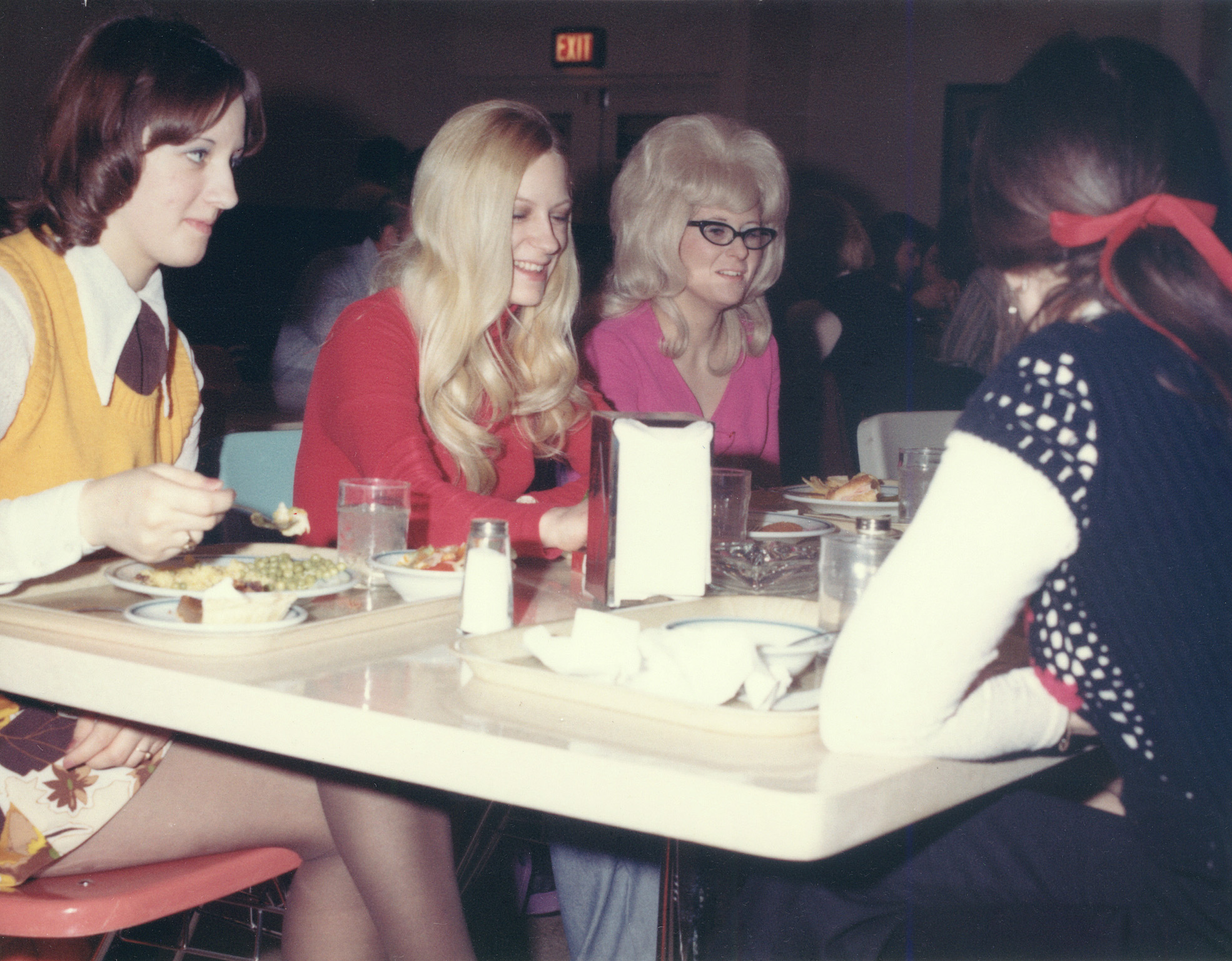
0106: Food service (Anonymous WECo engineer).
-
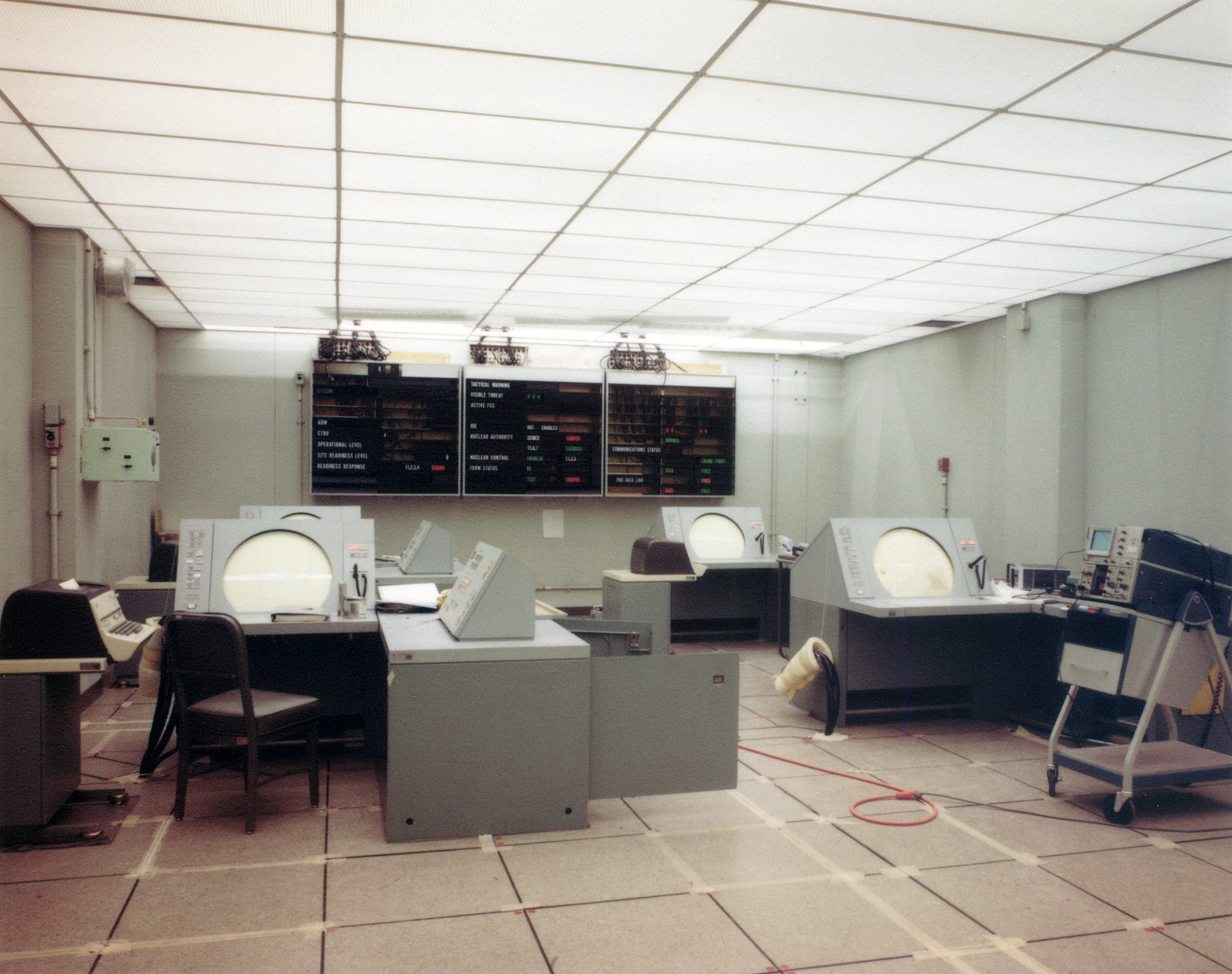
0064: BMDOC (Ballistic Missile Defense Operations Center) (Anonymous WECo engineer).
-
Provided the major tactical control of the local Safeguard system (SRMSC).
-
Equipment installation in progress.
-
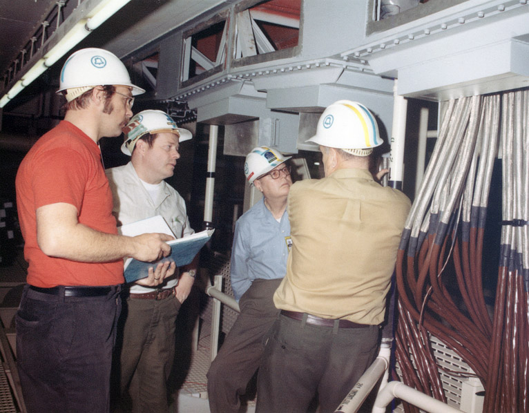
0038: Cable run discussion (Anonymous WECo engineer).
-
0000: Misc. Transmitter Recollections: Langdon Machine Shop (Ves Fulp).
PAR Complex Samples
-
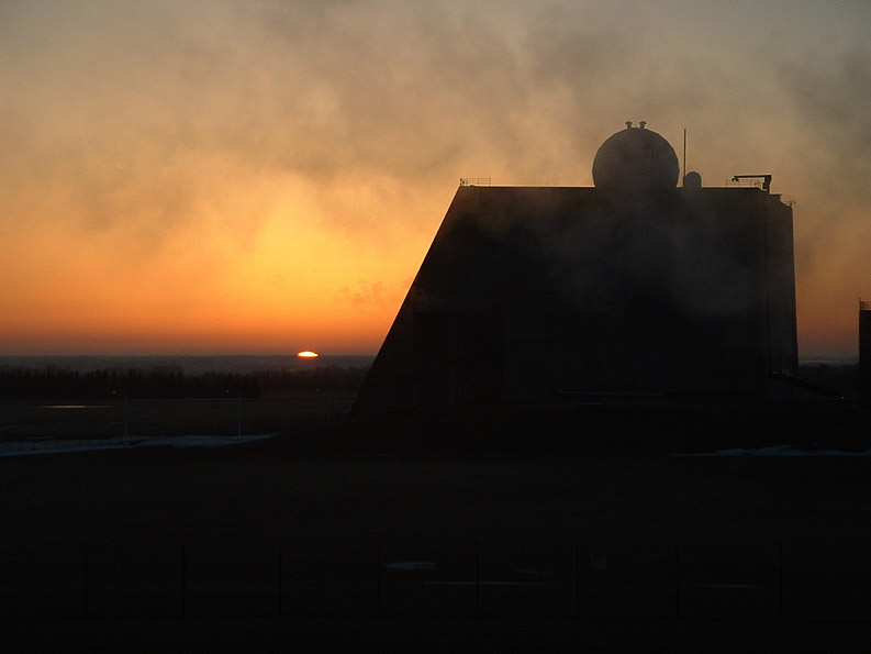
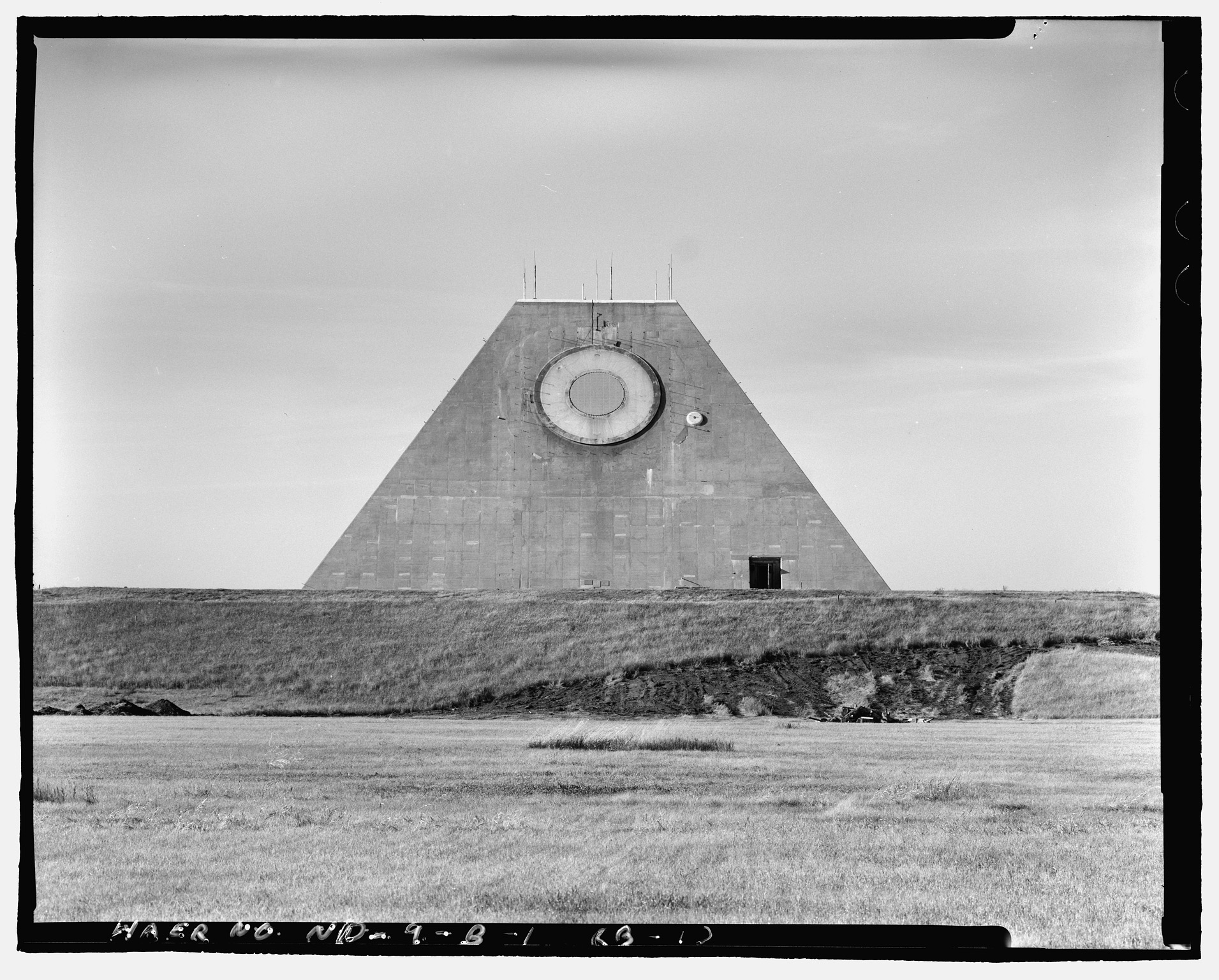
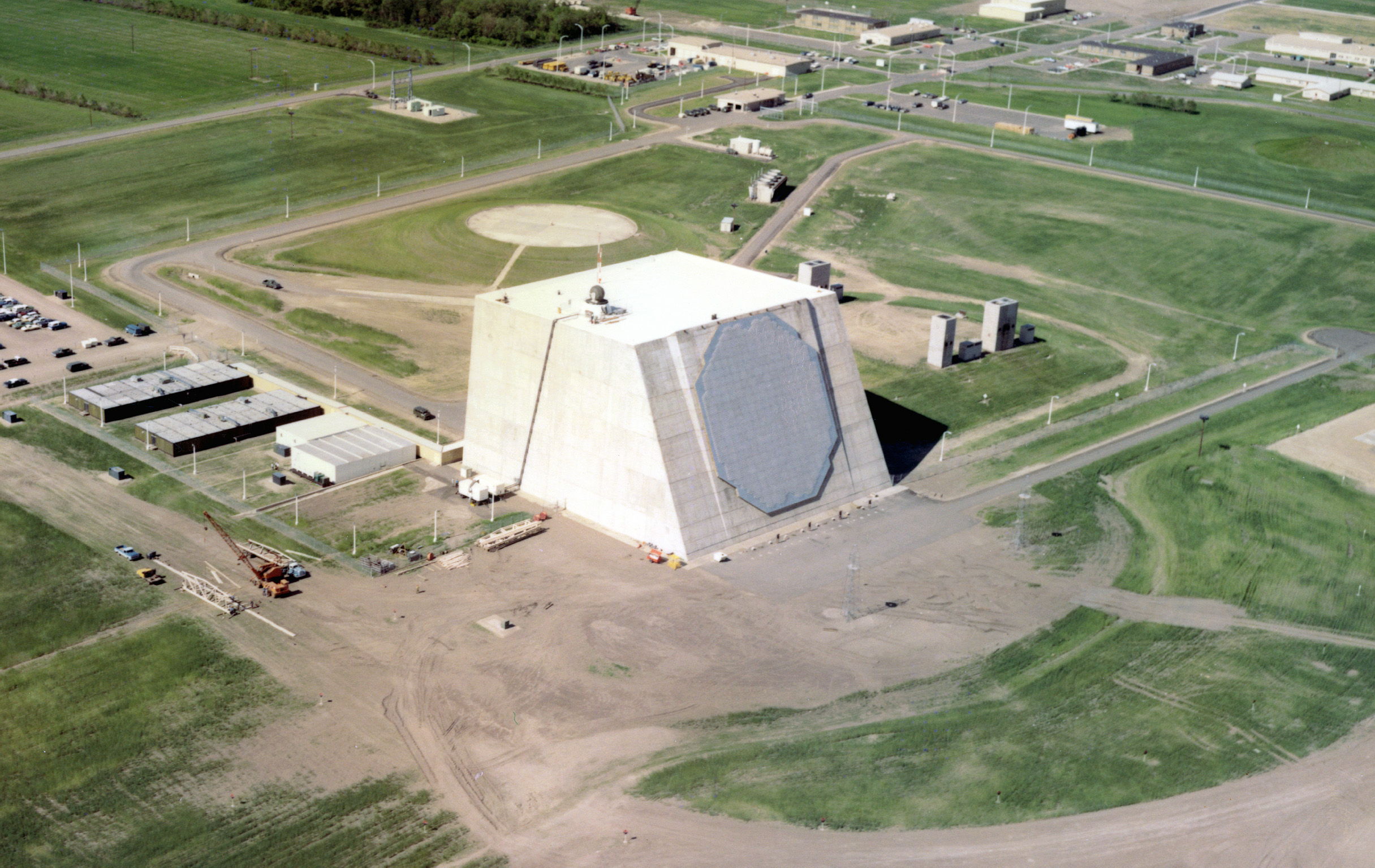
2003: PAR sunrise (Curtis Schweitzer).
-
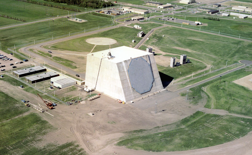
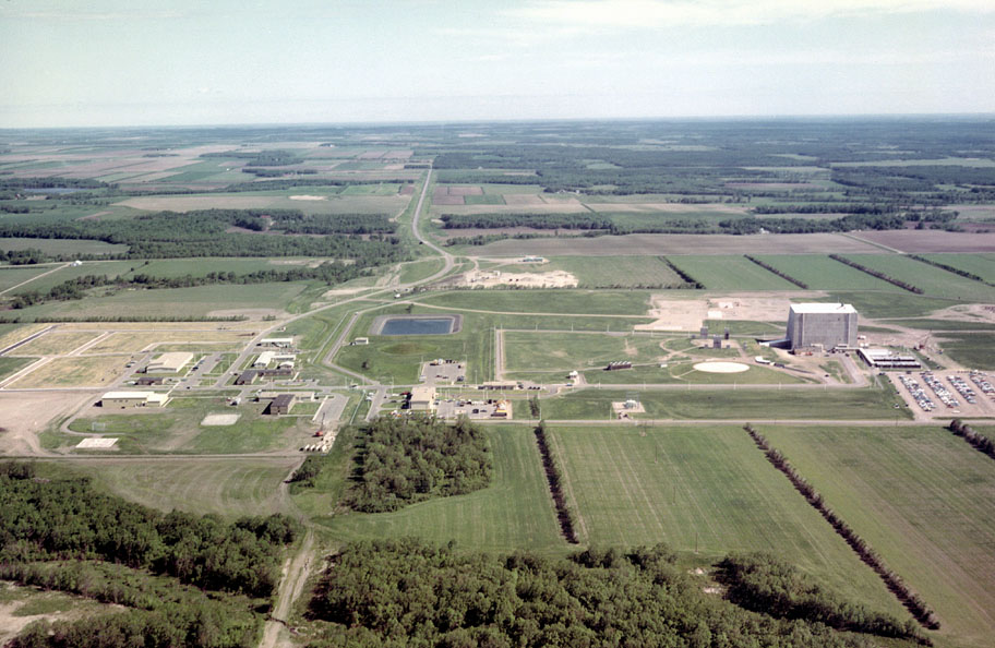
3002: Aerial view just after construction completed (Denis Abbott).
-
The Nike Hercules target tracking radar can be seen on the roof without its radome. It was used to help align the phased array radar.
-
The low buildings at the left rear of the PAR were used by the installation and test teams and were removed after activation.
-
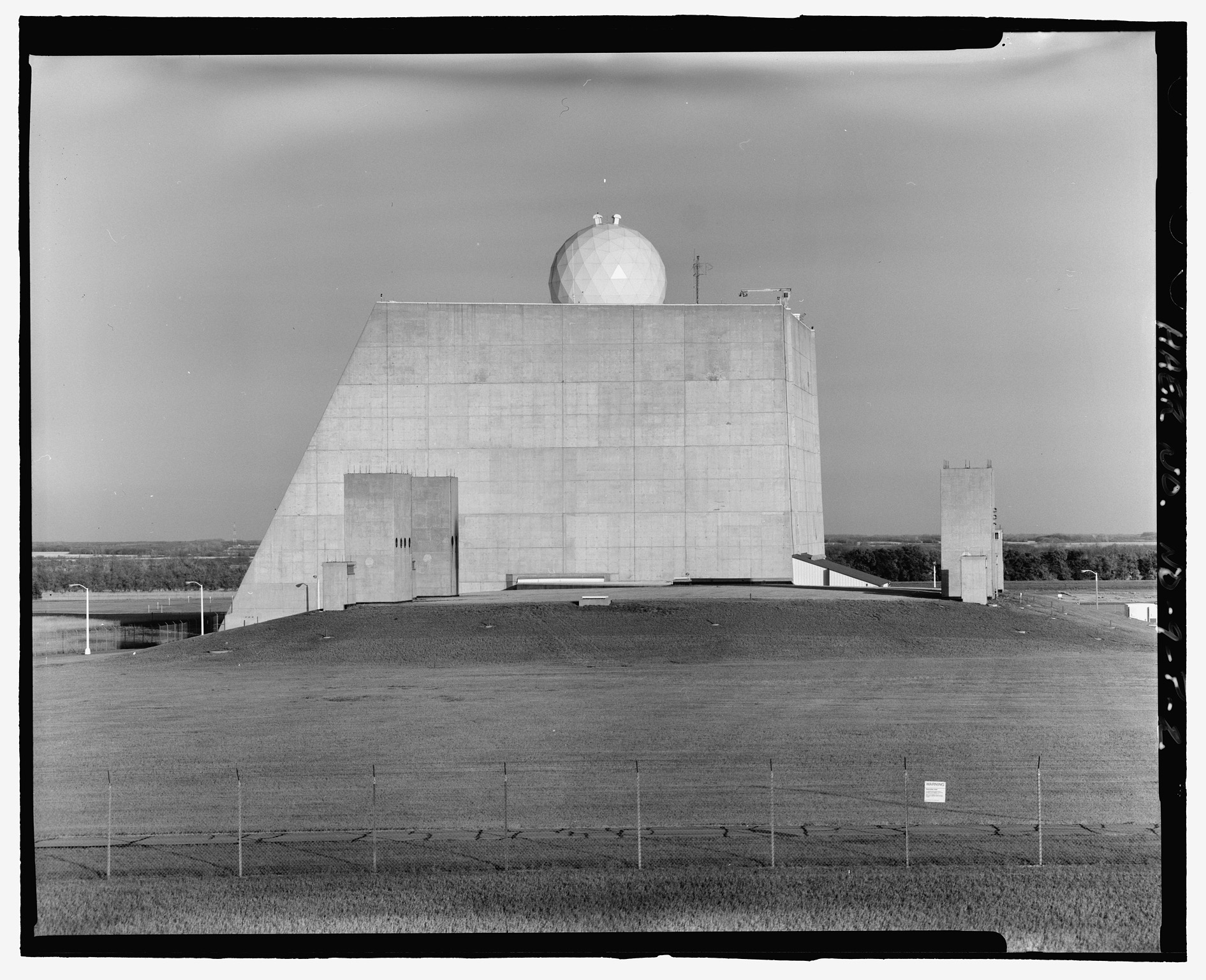
7394: View from the west, power plant in the foreground (HAER).
-
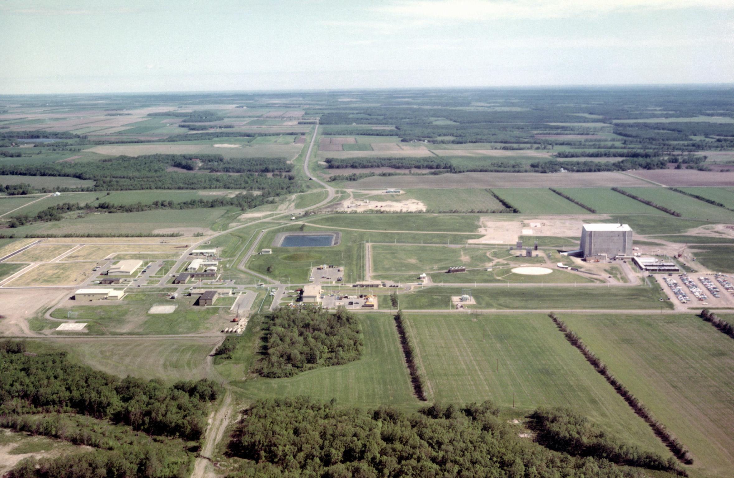
3006: Aerial view looking north (Denis Abbott).
-
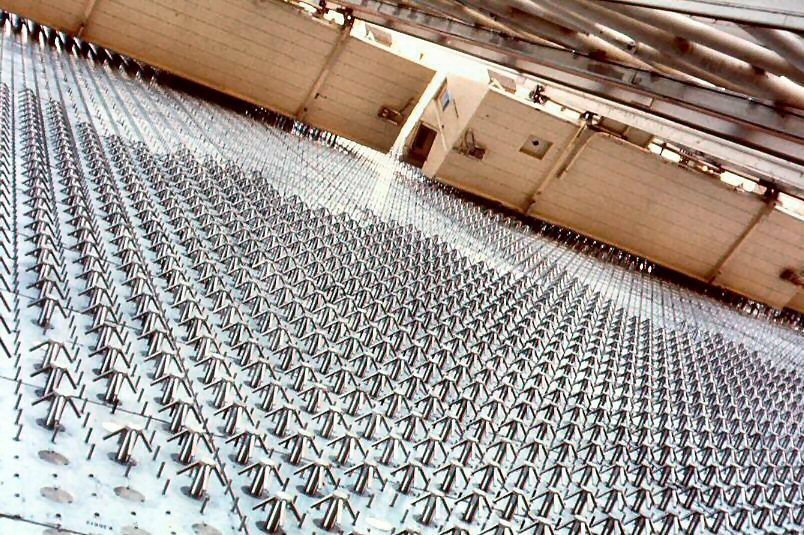
1080: Antenna element installation (Ves Fulp).
-
Underside of installation cabs and their supporting framework can be seen in upper right part of photo.
-
These cabs travelled up and down the antenna face to allow work to continue in all types of weather.
-
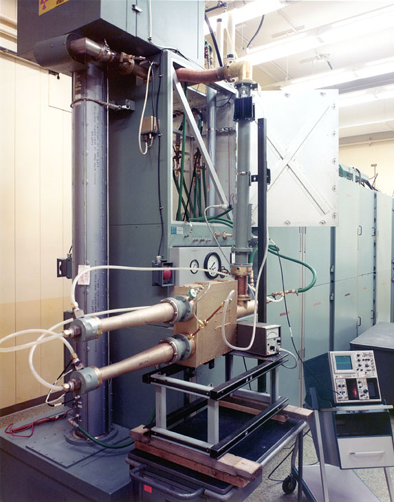
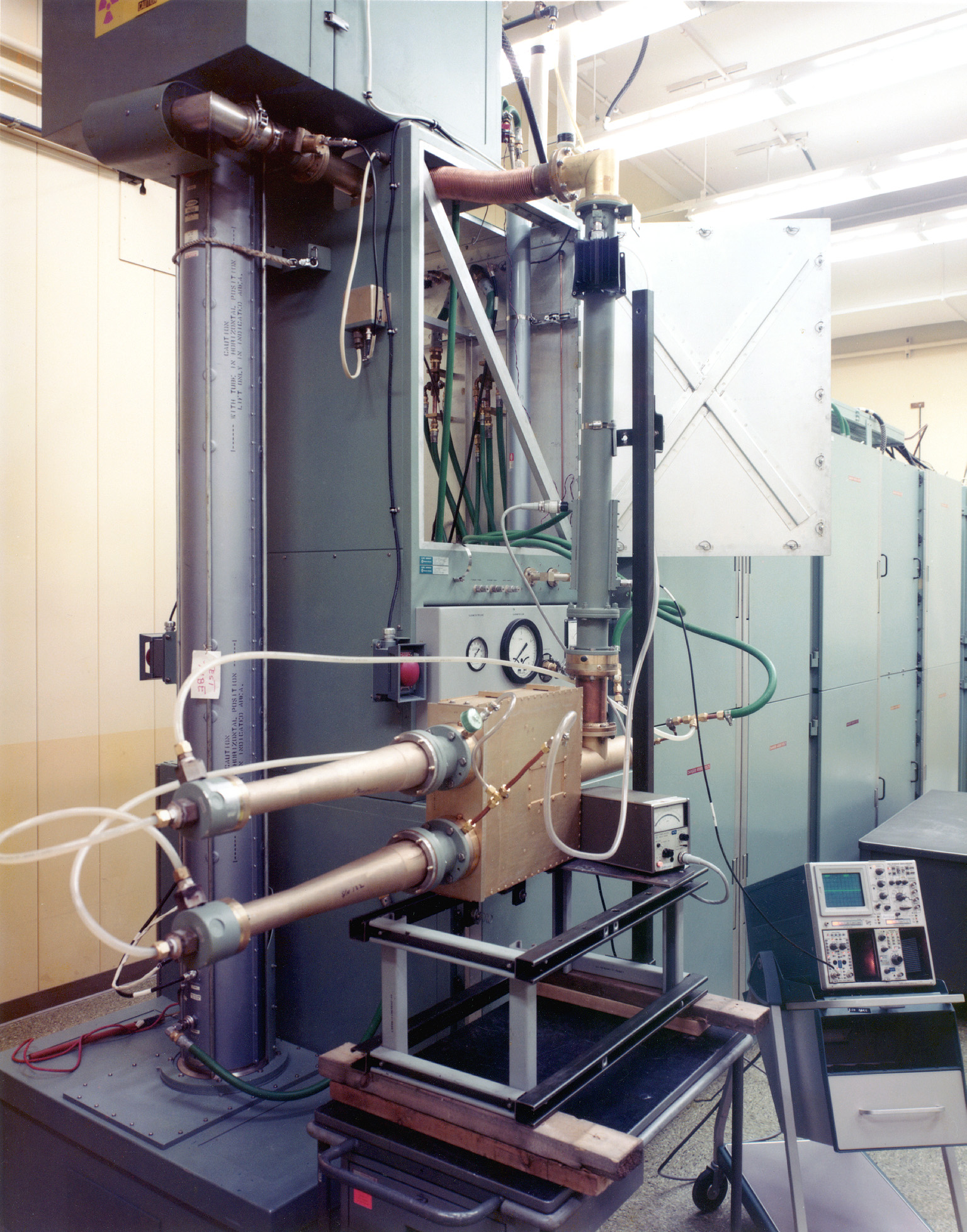
3026: Power splitter under test in TWT (Travelling Wave Tube) test area (Denis Abbott).
-
Vertical cylinder is a TWT that supplies the RF power for the PAR radar system. The TWT is approximately 8 feet long. This equipment is normally used to test TWT's prior to installation but in this photo it is configured to test the power splitter in the foreground. RF power leaves the tube at the top and is routed to the right and downward to the splitter under test.
RSL Samples
-
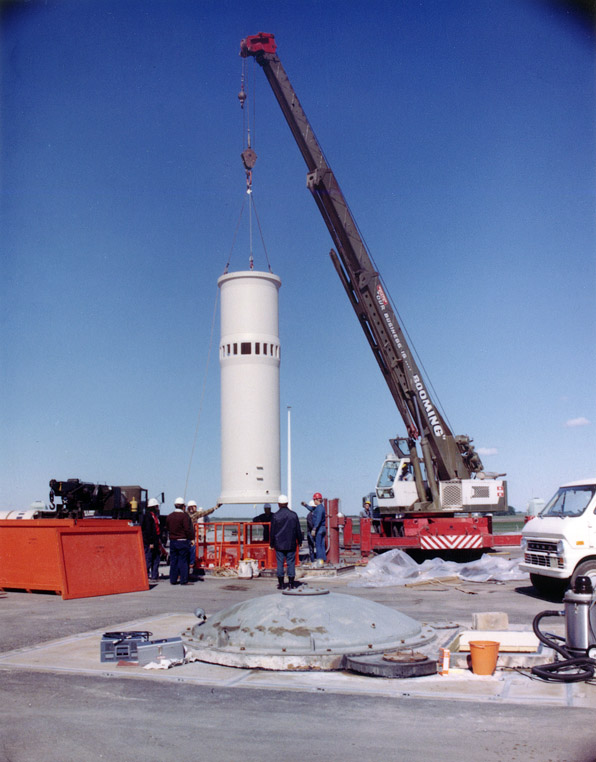
0128: Sprint missile silo liner (sleeve) being installed in the launch cell at RSL 2 (Anonymous WECo engineer).
-
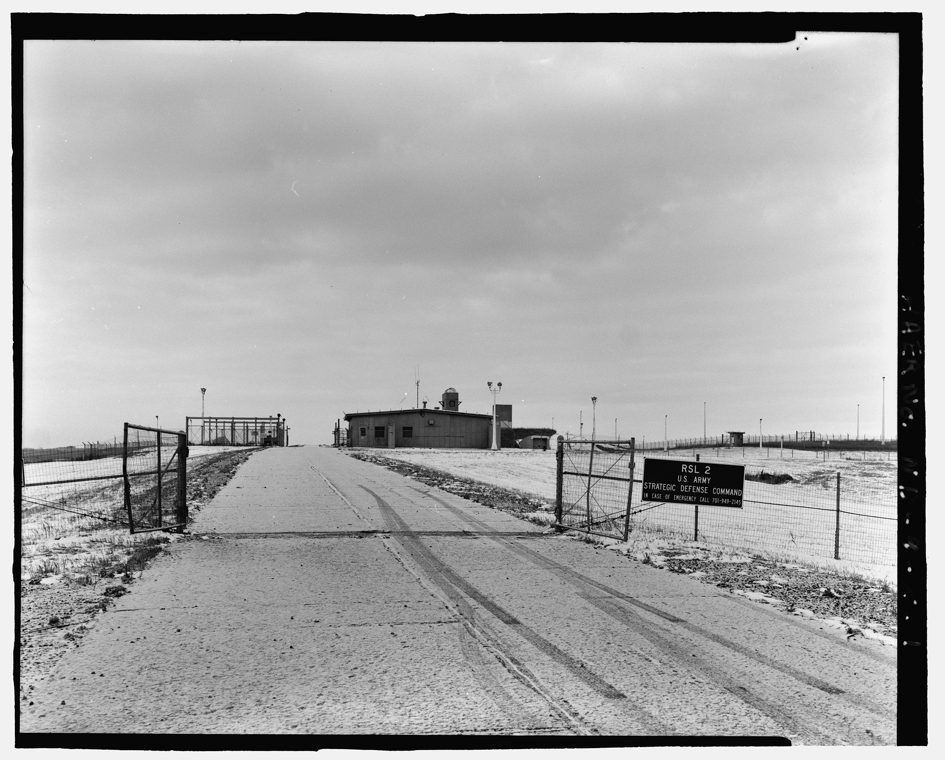
7474: RSL 2 main gate and LASS (limited area sentry station) (HAER).
-
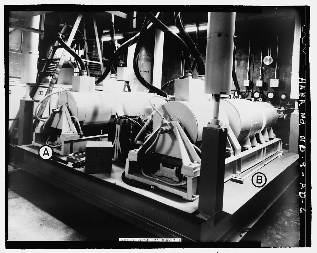
7487: RSL 3 power generation room #124, showing no-break units NB-1002 (A) and NB-1001 (B) (HAER).
-
This equipment consisted of a 150 horsepower, D.C. operational motor which drove, on each end of the extended shaft, a 70 kw generator and a 30 kw generator unit.
-
It was designed to provide continuous power service for launch equipment.
Miscellaneous Samples
-
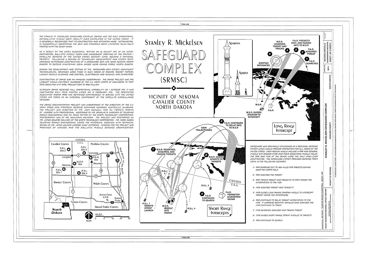
7001: Operational diagrams (HAER).
-
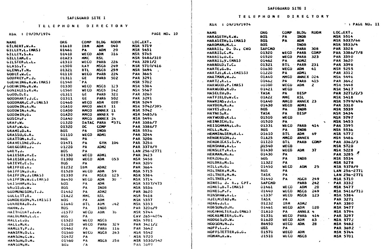
4001: Pages 10 and 11 from W/SC (Western/Subcontractors) Telephone Directory, Safeguard Site I, North Dakota Complex, September 1974 (Roger Thompson).
-
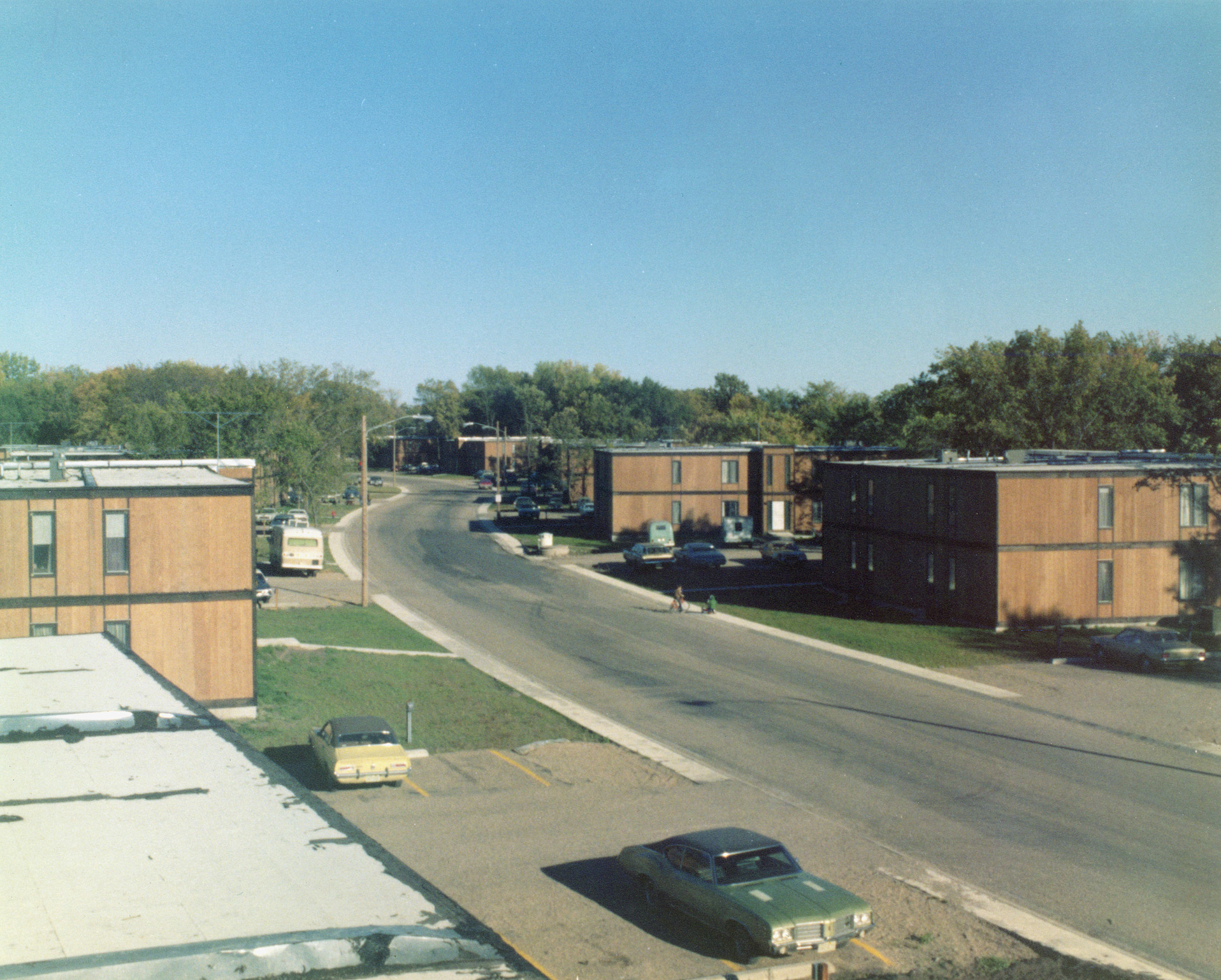
0161: 8-plex personnel housing units, Cavalier, ND (Anonymous WECo engineer).


