Photo Comments (use browser BACK button to return)
Photo Comments - MSR Complex
- Photo Sources:
-
0nnn: Anonymous WECo engineer -
1nnn: Ves Fulp -
Annn: Pam Bodenheimer Hiltner

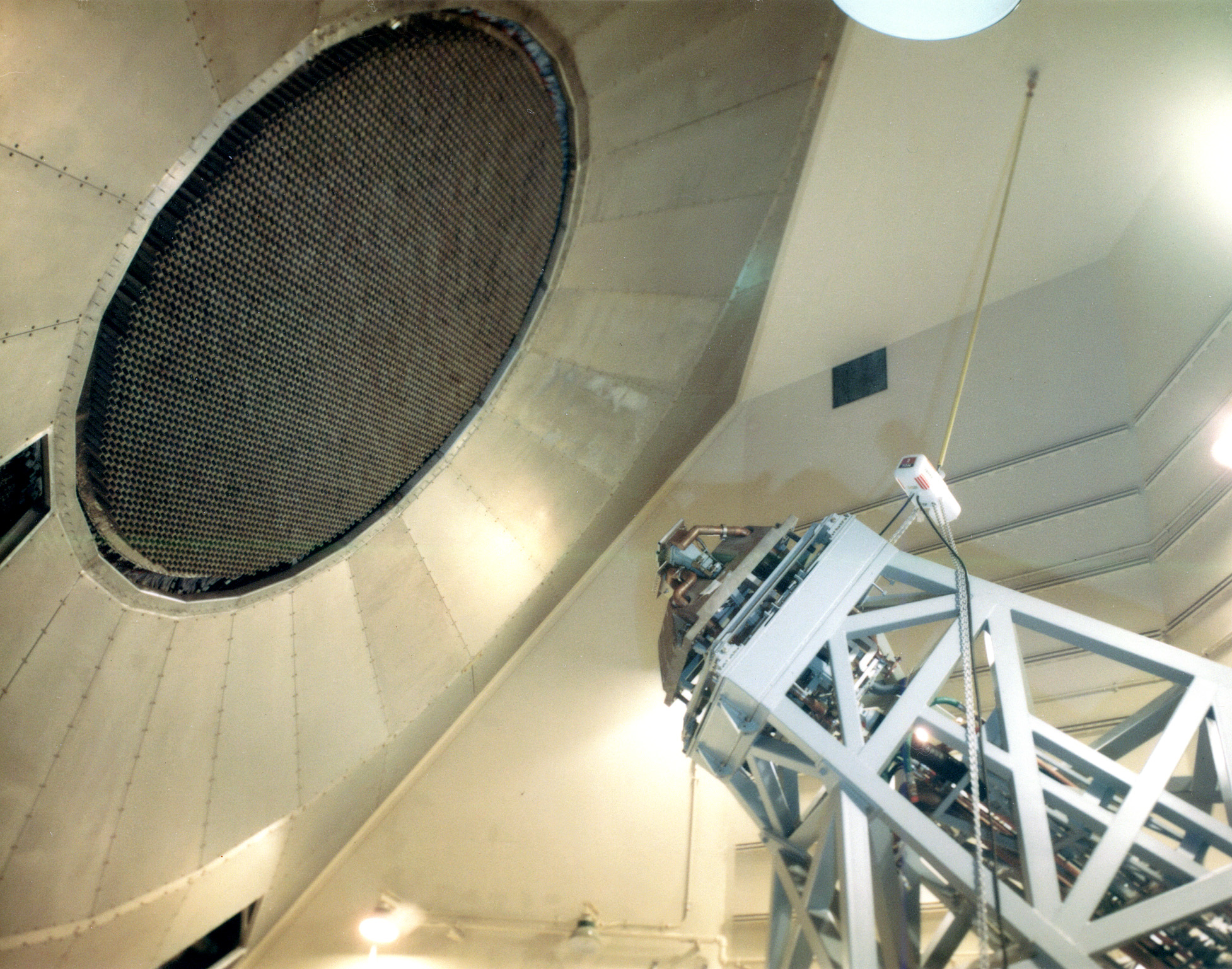
Ves Fulp (Anechoic Chamber):
The transmitter high power waveguide terminates at the feedhorn window in each of the four anechoic chambers. From the feedhorn window, the RF radiated power is space fed to the multitude of antenna elements which contain the electronics (delay circuits) that enable beam steering. The transmitter had no control of beam steering which was controlled by software originating from the digital data processor.
The transmitter high power waveguide terminates at the feedhorn window in each of the four anechoic chambers. From the feedhorn window, the RF radiated power is space fed to the multitude of antenna elements which contain the electronics (delay circuits) that enable beam steering. The transmitter had no control of beam steering which was controlled by software originating from the digital data processor.
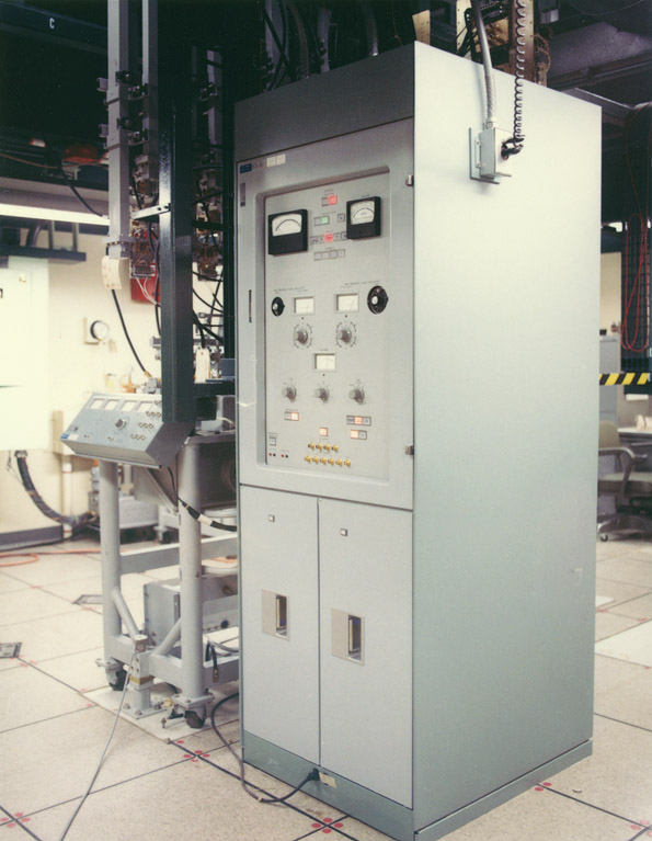
Paul Tudor (RF Receiver):
The parametric amplifier is on the left of the large cabinet. The mirrored meters read the cryogenic temperature inside the first of 3 varactor diodes which comprised the par-amp. The helium refrigerators were on the wall just behind the camera and ran the first stage just a few degrees above absolute zero. The par-amp vessel was evacuated to provide the necessary insulation aganst the cryo temperatures. The pump frequency for the varactors was located in the large cabinet as well. I think the box at the bottom of the par-amp vessel was the power supply for the ion trap.
I spent a lot of time keeping the cryogenic refrigerators online due to power failures. I only had to align the parametric amps once and it was no fun.
I recall using a mass spectrometer as a helium leak detector which later showed up at the Indianapolis Ham fest! The guys didn't know what they had. They also had the vacuum pumps which were probably already ruined because of the need for a special oil.
This was a cool job (no pun intended).
ABM R&D at Bell Labs, Chapter 7 (Closer view of the high power water cooled waveguides on high level waveguide switches):
Analytical work showed that, at the long pulse length and high average power levels of the MSR, a random arc would cause the copper waveguide wall to melt. This melting created copper particulate matter, which would be heated by the high average power resulting in more RF breakdown and continuous arcing.
The system remedy was to shut off the RF pulse as quickly as possible after an arc formed, preventing the generation of more particulate matter. This technique was known as "early-off."

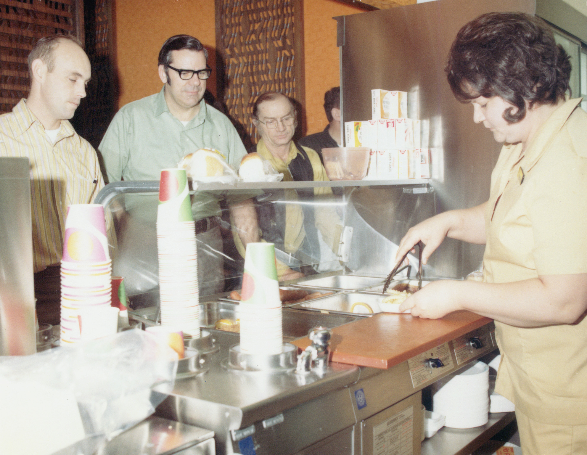
Mel Droege (Food Service - Left: Jim Curran, WECO quality assurance engineer (MSR); Center: Hal Smith, WECO quality assurance site supervisor (MSR)):
Hal Smith was my boss.
Hal Smith was my boss.
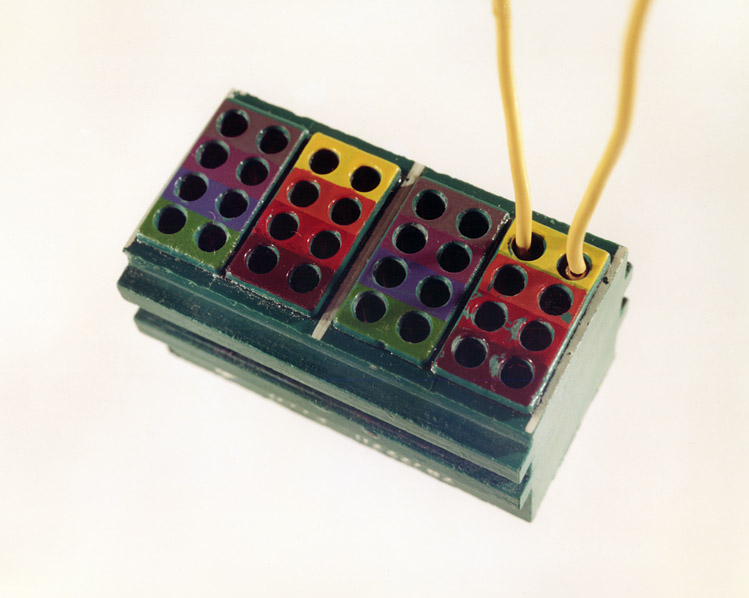
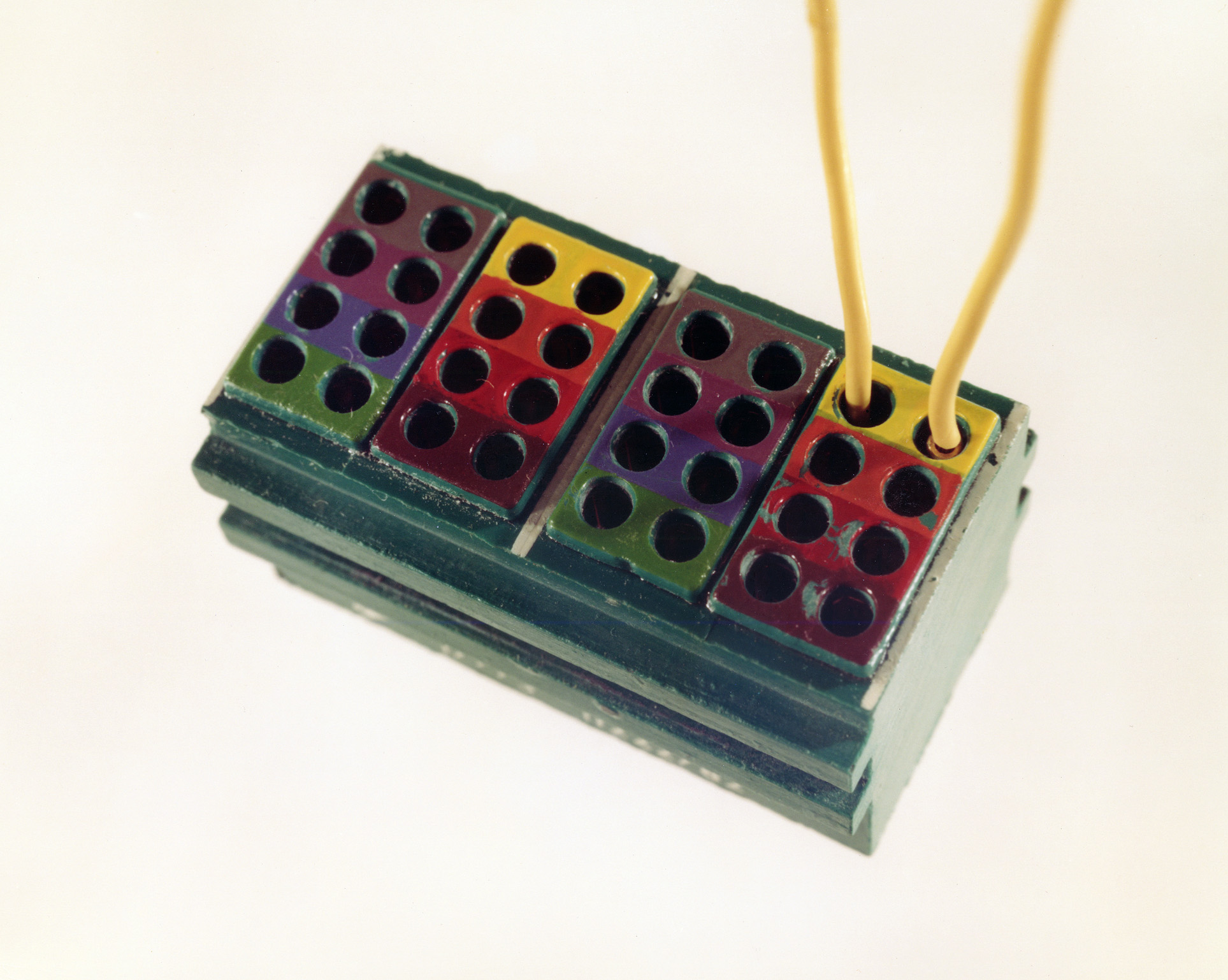
Mel Droege (MSR wire connector blocks):
Thousands of these were used to interconnect wiring. They became a quality control problem when many were found to contain cracks.
Thousands of these were used to interconnect wiring. They became a quality control problem when many were found to contain cracks.
Ves Fulp (Anechoic chamber):
It was the largest microwave oven in the world. The first time we fired that thing up, we melted telephones off the wall. There's an overhead crane that's in that room, and all the insulation on the cabling was melted.
It was the largest microwave oven in the world. The first time we fired that thing up, we melted telephones off the wall. There's an overhead crane that's in that room, and all the insulation on the cabling was melted.

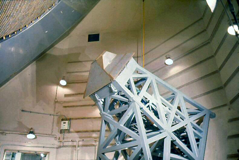
Ves Fulp (Winding up one of the klystron hats):
That was done as a joke. Our ancillary guy comes in one morning and brought that thing, it's a toy, and said we have to get a picture of that. I think that was a polaroid picture. That is the klystron hat on the left, that thing weighs about 6,000 pounds. It's 3/4 inch lead with a 1/4 inch stainles steel liner. I'm standing on one platform and you can see one on the other side.
That was done as a joke. Our ancillary guy comes in one morning and brought that thing, it's a toy, and said we have to get a picture of that. I think that was a polaroid picture. That is the klystron hat on the left, that thing weighs about 6,000 pounds. It's 3/4 inch lead with a 1/4 inch stainles steel liner. I'm standing on one platform and you can see one on the other side.
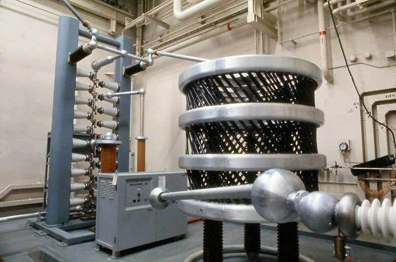
Ves Fulp (Crowbar (left), surge resistor (right)):
The high level transmitter's (HLT) electrical surge arrestor, is commonly called the "CROWBAR". Its primary purpose is to protect the klystron and other critical components from being destroyed by such events as arcing inside the klystron. Numerous fault protection circuits are incorporated to sense abnormalities throughout the HLT system, which in turn initiate the action that triggers the crowbar causing it to fire.
Typically, during normal operation, both klystrons are operated in parallel (combined power out) and should a major fault occur with one of the two klystrons, fault detection circuits will prevent damage to that particular klystron by firing the crowbar. Immediately, a unique array of waveguide switches will automatically reconfigure the switches to take the failed klystron off line and place the remaining klystron's output in the correct configuration for radiating solo out the antenna face. The waveguide switches operate in less than 100 milliseconds and during this time, the RF excitation to the good klystron is inhibited.
That little cabinet (in front of the tower) is a pulse generator assembly and contains the circuitry which initiates the firing of the crowbar when it receives certain fault generated signals. Spark gap break down (arcing across the gap) is a factor of the spark gap spacing. With the series of gaps, the accumulative gap spacing is such that they will not break down at the normal operating voltage of -150KV DC; however, in event of a critical fault, the pulse generator triggers action that causes the gap breakdown voltage to be exceeded. When this happens, the total energy stored in all three capacitor banks is discharged through this series of spark gaps to ground. The potential at the top of the crowbar is at -150KV DC and the base is at ground potential. Typically, an arc occurring inside the klystron would be detected by a current transformer monitoring the -150KV DC cable just prior to its entering the modulator tank. This would instantly activate a major fault resulting in the firing of the crowbar, which in turn discharges the full energy of the cap banks to ground in less than 5 microseconds. Without this protection, the klystron would be totally destroyed.
Side notes about the crowbar. Its noise when it fires is equal to the noise of a 5 inch cannon on a ship I was on. Once the crowbar is fired, the high voltage drops to zero, and can be brought back up to operating voltage within approximately 5 seconds. A favorite prank of ours during the many VIP tours was to manually test fire the crowbar as a tour group was leaving the transmitter control room. As they left the transmitter control room (which had fairly good sound proofing), they had to exit through the high voltage control room which had no soundproofing from the crowbar tower. There was of course a heavy duty safety wire fence. The base commanding general and other officers frequently brought tours through the HLT area. The general in particular, would often give me a nod to fire the crowbar as his tour group exited through the high voltage power supply control room. Of course, if we were supporting a mission, I could not do this.
During early testing, we were having trouble involving the high voltage run up and pulsing the klystron, and the quickest way to go from full load to no load was to fire the crowbar. This was so easy, we got carried away and were firing the crowbar in pretty rapid succession. At that time (during very early test phase), we were operating on motor generators using commercial power. In very short order, our going from full load to no load was too much for the power companies and we actually caused a total shut down of power for most of ND and Alberta, Canada. Their switch gear would not handle the abrupt changes in load and did cause damage at the power stations. To them, it was kind of like a rapid series of lightening strikes.
A little trivia:
The crowbar tower weighed 5115 pounds, was 7'8" x 6'10" x 14'5" high in size
The pulse generator assembly weighed 506 pounds, was 5' x 3' x4' high in size
For more information, see "Final Power Amplifier Overview" on the MSR High Level Transmitter (HLT) Detail page.
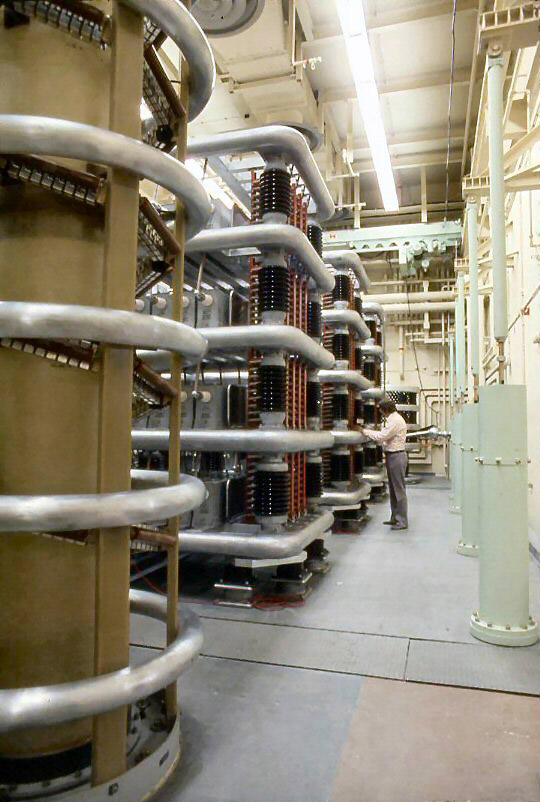
Ves Fulp (Capacitor banks with rectifier stack partially visible on left):
With those big capacitor units, we had what we called swinging gates. And for each one of those layers, there's a separate big ball that comes around and hits those the moment you unlock that door. Even though the shorting gate is designed to short out any residual charge remaining, transmitter engineers would still use the "shepherd's hook" to tap each corona ring, then leave it hanging to the top ring. The cap bank shepherd's hook is on a long 10ft wooden pole with a heavy braided flexible cable connected between the hook and ground.
Each of the 3 capacitor banks contained ninety-six 40,000 volt capacitors, which received lots of respect from anyone entering the high voltage room. The shorting gates were opened and closed automatically by the Kirk Key safety system. By design, personnel could not go into a high voltage room without using the Kirk Key. The Kirk Key block controlling entry contained two keys; to enter, the engineer turned both keys, then removed one key and put it into his pocket -- this was his first line of safety as turn-on of high voltage was totally disabled. Next, he would verify that the shorting gate had actually closed, then he would hang a "shepherd's hook" on each cap bank as well as the high voltage lead going through the wall into the modulator tank. Upon leaving the high voltage room, this procedure was reversed before the high voltage circuits could be energized.
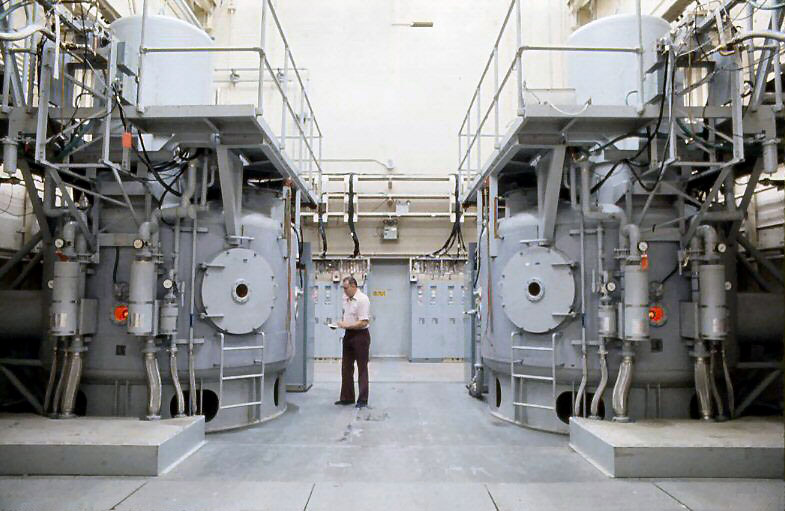
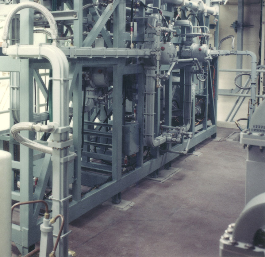
Ves Fulp (Modulator tanks, commonly called klystron tanks):
Damaging arcs occasionally occurred inside the tank involving components other than the klystron. Typically, one of the high voltage capacitors would break down and literally explode resulting in massive contamination of the transformer oil. Any short circuit or other malfunction involving 150KV can do a lot of damage in microseconds. Failures involving contamination required complete draining of the oil and transferring it to a dirty oil storage tank. Filter presses, part of the ancillary group, would reprocess/reclaim the dirty oil back to high dielectric purity.
To clean the tank of the carbon contamination, one or two men would strip down to their skivvies, go inside the tank, remove the contamination, flush the tank interior several times with clean oil, and scrub the ceramic on both switch tubes and klystron with Everclear; yes, this high proof alcohol worked great in cleaning carbon tracks or burn smudges. After the men left the tank, it was then refilled with oil from the clean oil storage tank. It should be mentioned that there were two access hatches on the tank, and a heavy exhaust fan with a large flexible hose (we called it an elephant trunk) was used to insure good ventilation for the men inside.
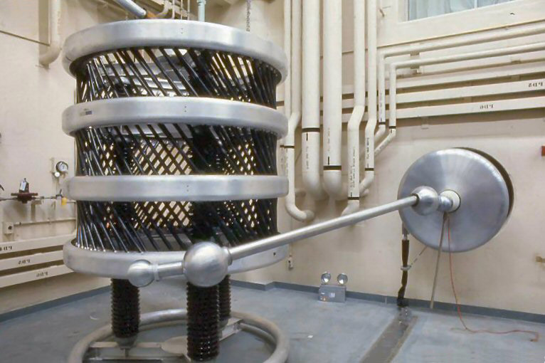
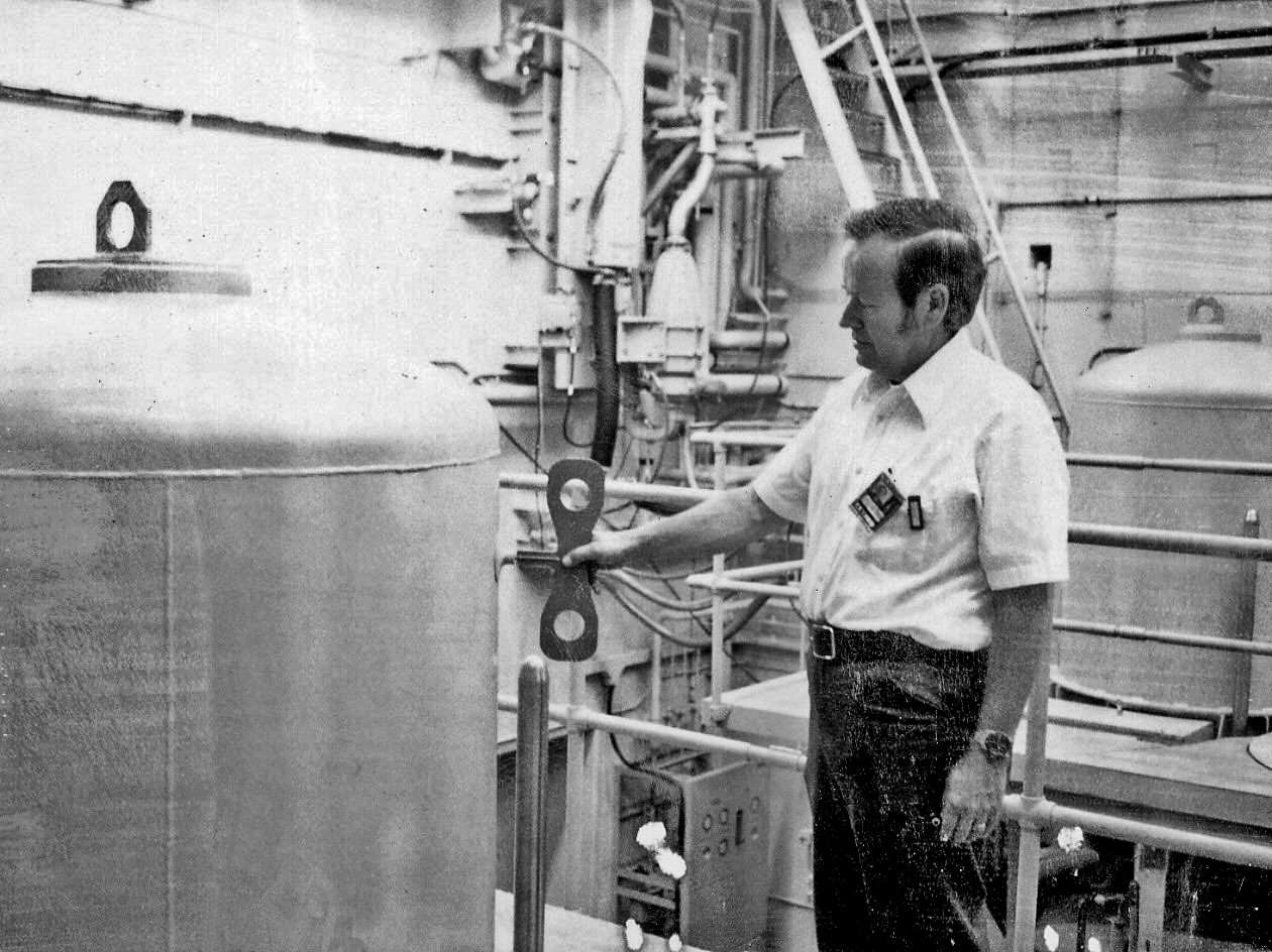
Ves Fulp (Surge resistor):
The round corona ring encircles the high voltage lead going into the klystron room. On the far side of the wall, the -150KV conductor enters the modulator tank.
Everything had to be perfectly smooth, even the hardware used to hold down components had to have all sharp edges sanded smooth to prevent corona. Corona is the ionization of the nitrogen in the air, caused by an intense electrical field. Electrical corona is invisible during the day and requires darkness to see at night. A sizzling audible sound, or smell of ozone is a good indication that corona is present. In the presence of sensitive electrical equipment, it presents a very unwelcome noise source.
The little hook with the little red wire on the end of the stick hanging on the high voltage lead just in front of the corona shield is called a "shepherd's hook". They are used in many places throughout the transmitter high voltage circuits, especially where high voltage capacitors are present. Areas requiring Kirk Key access have shorting bars/gates that are automatically activated; still, a smart/wise engineer will use the "shepherd's hook." I have seen two cases where an automatic shorting bar failed to operate properly and/or an individual failed to use it, one resulting in death and the other resulting in near death.
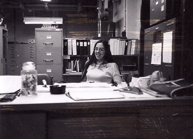
Ves Fulp (Miss Transmitter Room - Pamela Bodenheimer - circa 1974):
She was the daughter of a Western Electric friend (and a frequent golf companion). I hired her as a receptionist, typist, and all around helper. Because of high level x-rays, microwave and high voltage, she controlled entry and the issuance of dosimeters to all visitors as well as film badges to all who worked in the transmitter room as well as typing, filing, making coffee, etc. She came to my group when two previous receptionists left because they could not tolerate the high noise levels. Being young and her first job, she was a perfect match for the transmitter environment and work personnel.
She was the daughter of a Western Electric friend (and a frequent golf companion). I hired her as a receptionist, typist, and all around helper. Because of high level x-rays, microwave and high voltage, she controlled entry and the issuance of dosimeters to all visitors as well as film badges to all who worked in the transmitter room as well as typing, filing, making coffee, etc. She came to my group when two previous receptionists left because they could not tolerate the high noise levels. Being young and her first job, she was a perfect match for the transmitter environment and work personnel.
End of page.