A01 :
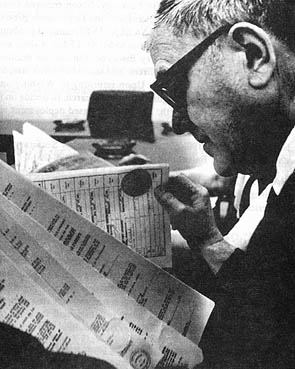
April 1, 1970 -- Final review of bid documents was made by Emil Vuch, Chief Legal Counsel of the Huntsville Division, prior to contract award to Morrison-Knudsen Company and Associates. Source (2).
(295 x 369 = 48k) Show | Omit descr (002938) (485 x 607 = 96k) Show | Omit descr
A02 :
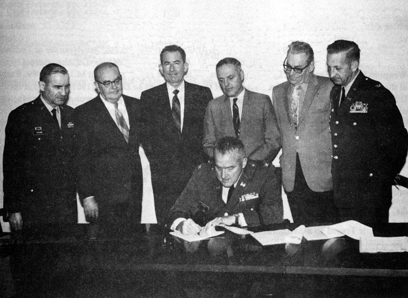
A $137,858,850 contract for construction of the nation's first Safeguard ballistic missile defense system facilities being installed in the area of Grand Forks, ND was signed by Colonel Robert W. McBride, Huntsville Division Contracting Officer. Source (2).
Looking on were Brigadier General R.P. Young, Huntsville Division, Engineer; Joe Leas, Executive Vice President, C.H. Leavell & Co.; E.M. Armstrong, Vice President, Morrison-Knudsen Co., Inc.; Lee Rowe, Vice President, Peter Kiewit Sons' Co.; S.E. Davidson, Regional Vice President, Fischbach and Moore, Inc.; and Colonel Bates C. Burnell, Huntsville Deputy Division Engineer.
(404 x 295 = 043k) Show | Omit descr (002939) (808 x 590 = 125k) Show | Omit descr
B01 :
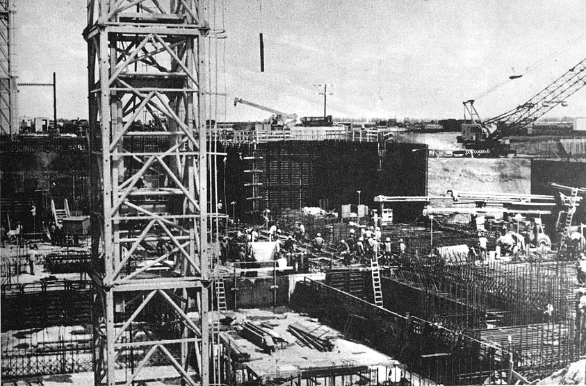
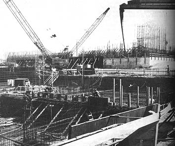
Forms and resteel await the placement of concrete at the MSCB during summer 1970. Source (2).
(447 x 295 = 070k) Show | Omit descr (002908) (843 x 556 = 196k) Show | Omit descr
B02 :
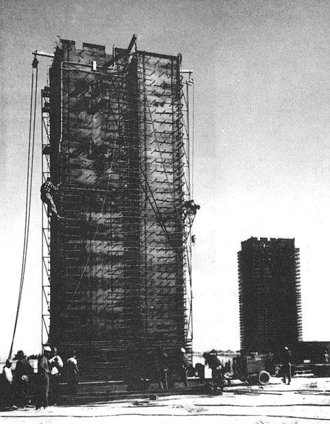
43 foot high midsection of the Spartan launch tube and exhaust chamber being prepared for insertion into the Spartan launch cell at the MSR site during October 1970. Source (2).
(295 x 379 = 47k) Show | Omit descr (002910) (482 x 620 = 99k) Show | Omit descr
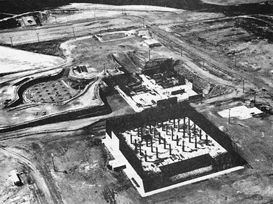
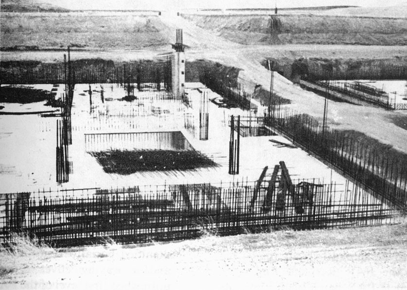
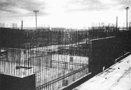
B03 :
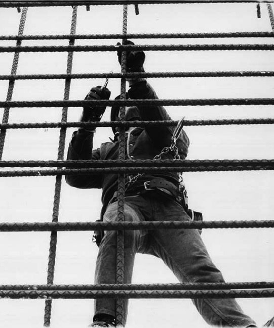
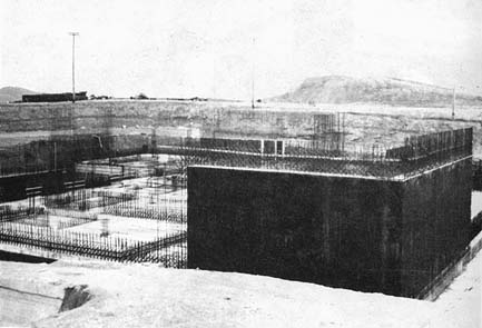
Tying rebar-construction began on the nuclear hardened facilities in 1970. Source (3).
(295 x 354 = 45k) Show | Omit descr (002965) (541 x 649 = 88k) Show | Omit descr
B04 :
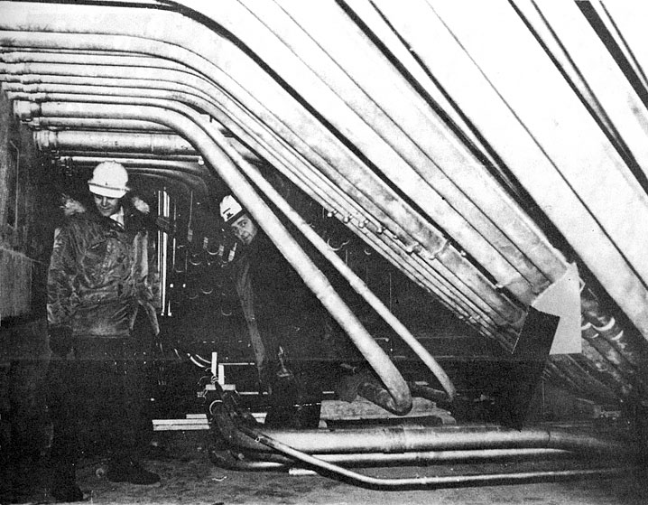
Miles of conduit being installed in the MSR power plant during the subzero weather in January 1971. Source (2).
(379 x 295 = 059k) Show | Omit descr (002913) (718 x 559 = 146k) Show | Omit descr
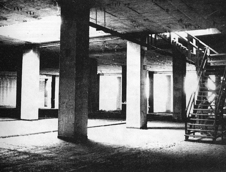
B05 :
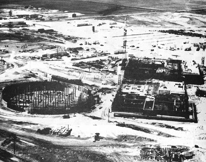
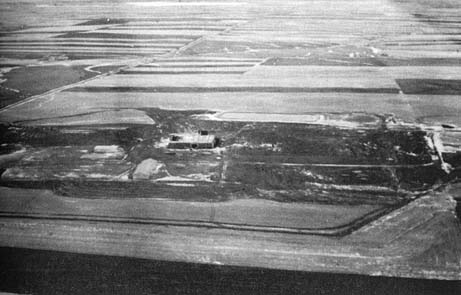
The MSR site in June 1971 during construction. Source (2).
At left is the 7 1/2 million gallon capacity heat sink which will be underground when completed.
At right center is the 17.3 megawatt power plant with its roof being closed in.
Directly behind the power plant is the Missile Site Control Building (MSCB) with the third floor structure being roofed in and the radar turret starting to be formed up.
(373 x 295 = 067k) Show | Omit descr (002933) (781 x 617 = 184k) Show | Omit descr
B06 :
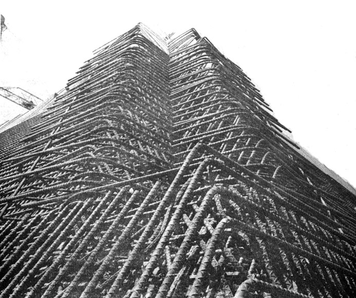
An intricate mass of rebar for the MSR turret wall, July 1971. Source (2).
(352 x 295 = 062k) Show | Omit descr (002912) (693 x 580 = 147k) Show | Omit descr
B07 :
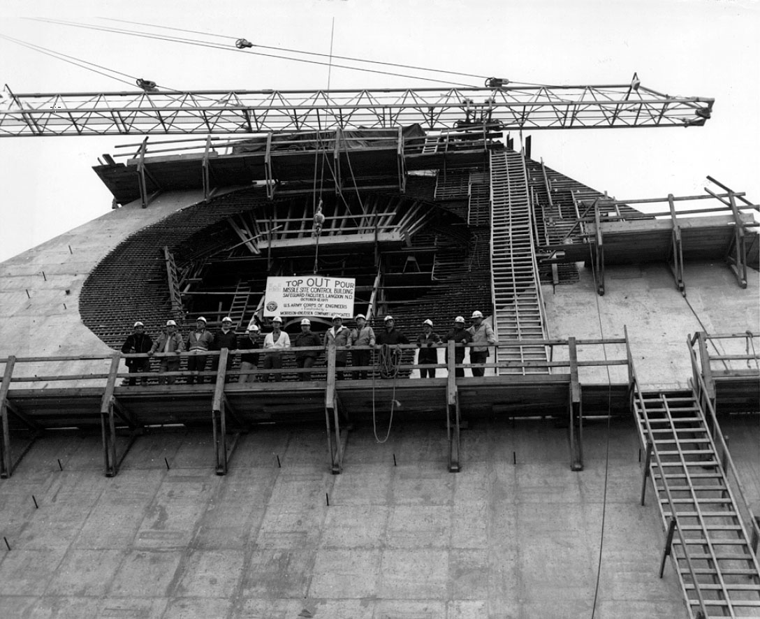
Despite weather conditions, which ranged from -40oF to 100oF, the Top-Out Pour for the Missile Site Control Building took place on 12 October 1971. Source (3).
(0362 x 295 = 047k) Show | Omit descr (002963) (1088 x 886 = 211k) Show | Omit descr
B08 :
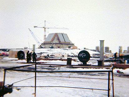
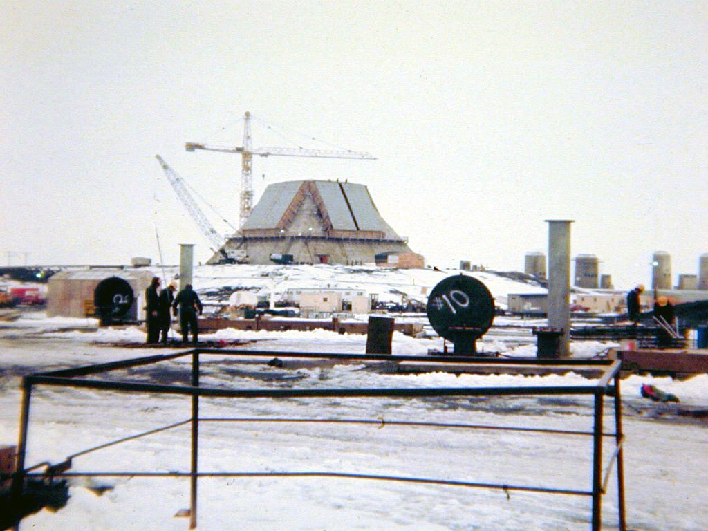
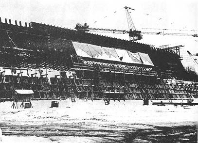
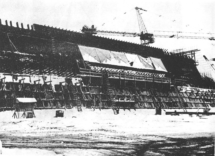
Despite the snow cover, work continues on Sprint silos and the MSR. Source: newspaper photo.
(0413 x 310 = 068k) Show | Omit descr (002945) (1024 x 768 = 181k) Show | Omit descr
B09 :
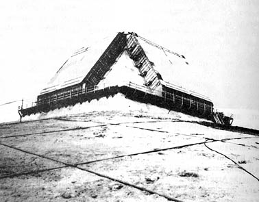
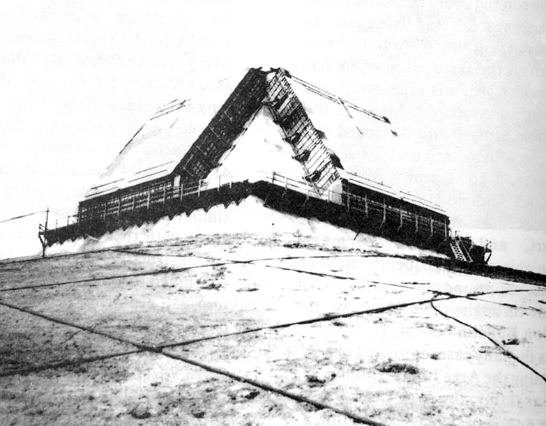
Closer view of the MSR turret with winterization in place to allow work to continue on the antenna faces. April, 1972. Source (2).
(378 x 295 = 045k) Show | Omit descr (002927) (783 x 611 = 109k) Show | Omit descr
B10 :
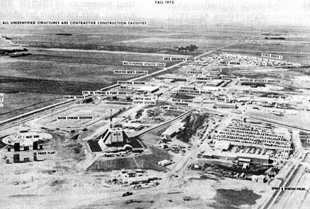
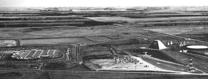
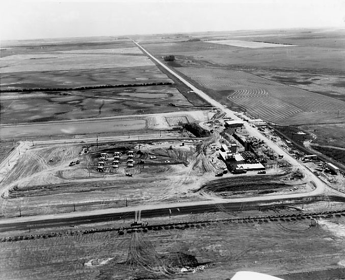
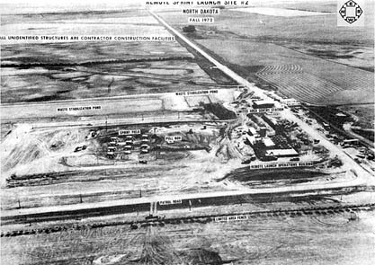
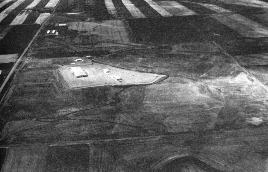
MSR site looking toward the southwest, Fall 1972. Source (2).
Major facilities are labelled. All unidentified structures are contractor construction facilities.
(437 x 295 = 065k) Show | Omit descr (002918) (894 x 603 = 182k) Show | Omit descr
B11 :
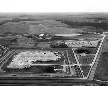
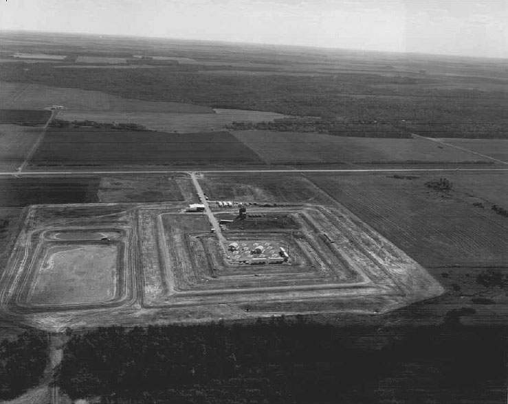
Construction of the MSR complex is mostly complete, but the temporary parking lot is still in place (just to right of center) for access to the personnel entrance on level 2 of the MSCB (just below the right face of the MSR). Source (1).
(368 x 295 = 047k) Show | Omit descr (002903) (677 x 543 = 111k) Show | Omit descr
B12 :
Another view from the west of the mostly completed MSR complex. Source (2).
The heat sink and power plant intake/exhaust stacks are at the extreme right.
Spartan and Sprint missile fields are at the extreme left.
A rare view of the two radar test towers (lower right corner and opposite side of the MSR turret).
A rare view of both MSCB entrances. The main entrance is below and just to the left of the white oval of the heat sink. The personnel entrance is just above and right of the temporary parking lot.
(600 x 229 = 48k) Show | Omit descr (002930) (842 x 321 = 83k) Show | Omit descr
C01 :
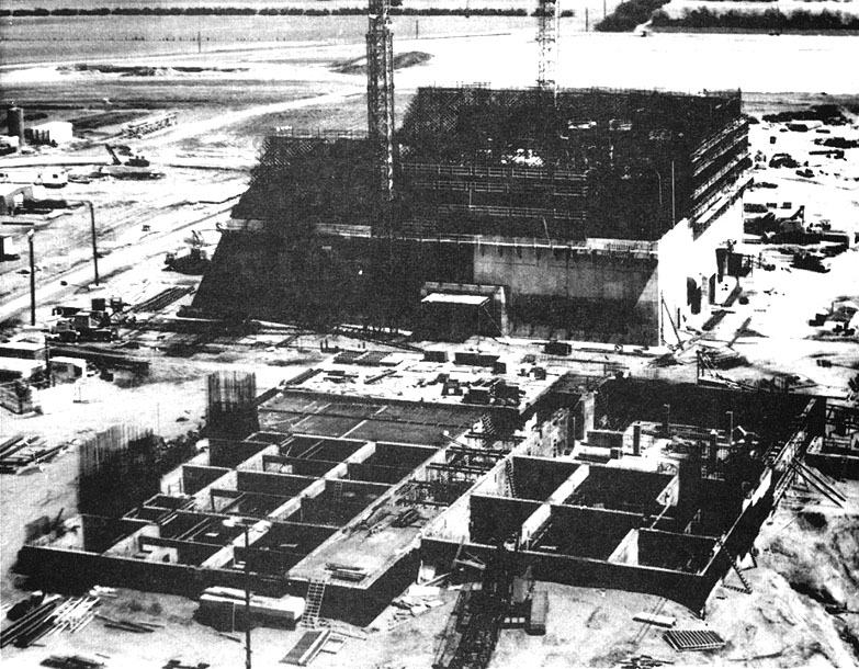
The PAR construction site in mid summer 1970. Source (2).
Looking across the power plant which will be all underground when completed, the PAR building begins to take shape in the background.
(354 x 295 = 056k) Show | Omit descr (002909) (711 x 592 = 157k) Show | Omit descr
C02 :
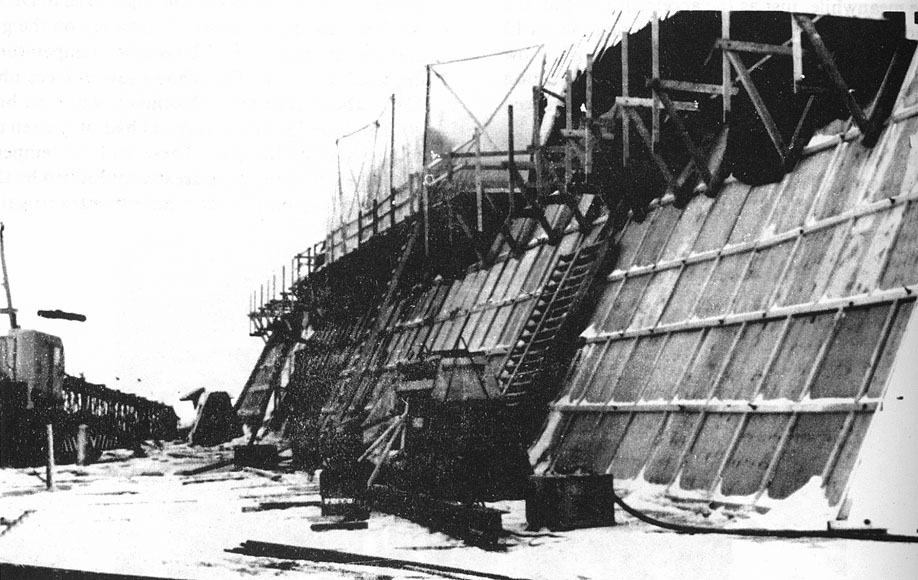
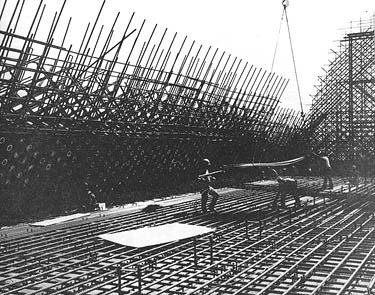
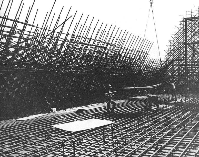
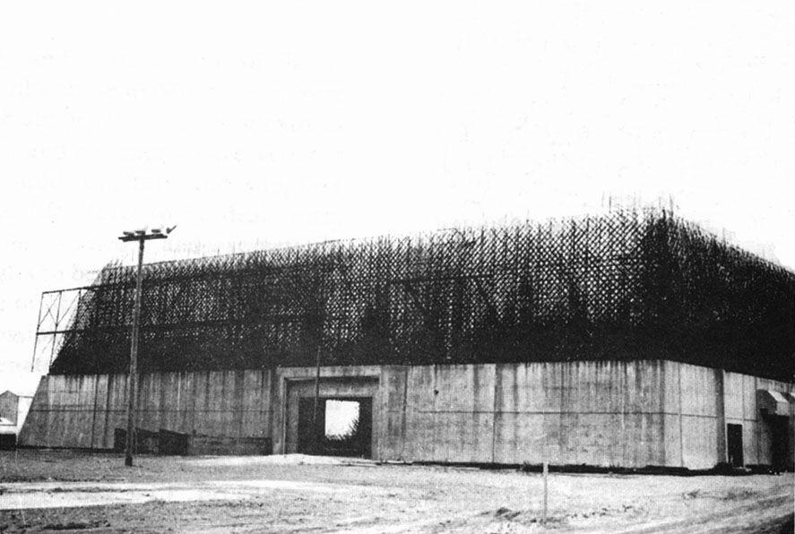
Winterized north wall or face of the PARB showing the radar penetration holes. March 1971. Source (2).
The face slants back at a 25 degree angle and will rise over 125 feet in the air.
(407 x 295 = 058k) Show | Omit descr (002936) (852 x 618 = 177k) Show | Omit descr
C03 :
Another view of the winterized "A" (Antenna) wall. March 1971. Source (2).
(467 x 295 = 053k) Show | Omit descr (002937) (918 x 580 = 144k) Show | Omit descr
C04 :
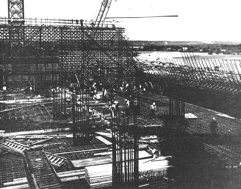
A view of the PAR site during June 1971, looking across the top of the 14.3 megawatt power plant toward the west well of the PAR building. Source (2).
(379 x 295 = 069k) Show | Omit descr (002932) (783 x 610 = 188k) Show | Omit descr
C05 :
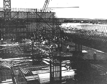
The third floor northwest corner of the PARB under construction in June 1971. Source (2).
(377 x 295 = 062k) Show | Omit descr (002934) (779 x 610 = 199k) Show | Omit descr
C06 :
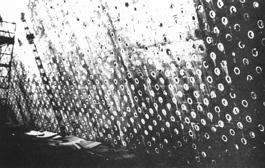
Radar tube penetrations in the radar face of the PARB under construction in June 1971. Source (2).
(375 x 295 = 070k) Show | Omit descr (002935) (776 x 610 = 206k) Show | Omit descr
C07 :
The face plane of the PARB as it appeared in late June 1972. Source (2).
(396 x 295 = 056k) Show | Omit descr (002929) (817 x 608 = 185k) Show | Omit descr
C08 :
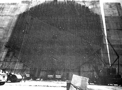
PARB "A" (antenna) wall showing penetration from the inside. Source (2).
(465 x 295 = 067k) Show | Omit descr (002915) (906 x 575 = 157k) Show | Omit descr
C09 :
Air handling equipment installed in the PARB. Source (2).
(461 x 295 = 046k) Show | Omit descr (002914) (904 x 579 = 141k) Show | Omit descr
C10 :
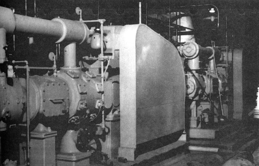
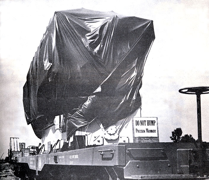
The first of the diesel engines and auxiliaries skid to arrive at the PAR site from Cooper Bessemer Co., Grove City, PA. Source (2).
(343 x 295 = 050k) Show | Omit descr (002911) (705 x 607 = 165k) Show | Omit descr
C11 :
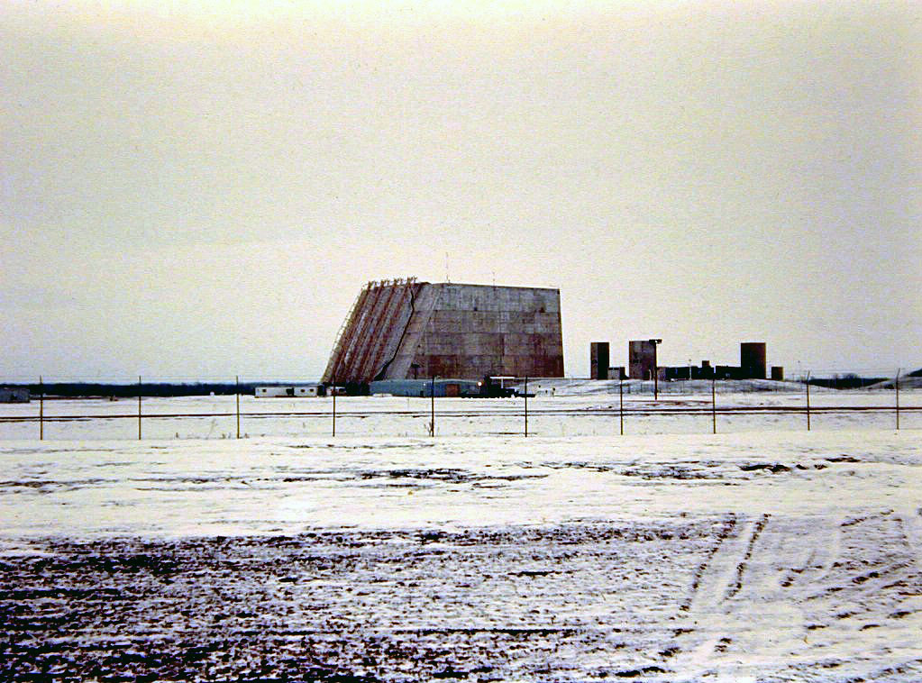
View from the west of the PARB under construction. Source: newspaper photo.
The support structure for the antenna element installation cabs is in place over the PAR's face.
(0398 x 295 = 050k) Show | Omit descr (002944) (1023 x 758 = 233k) Show | Omit descr
C12 :
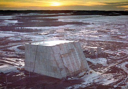
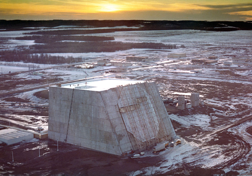
Sunset view of the PARB under construction, antenna element installation in progress. Source (5).
The antenna element installation cabs are in place over the PAR's face.
(422 x 295 = 049k) Show | Omit descr (003113) (846 x 592 = 149k) Show | Omit descr
C13 :
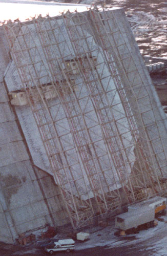
Closer view of the antenna element installation cabs and supporting framework above the PAR face. Source (5).
(326 x 0500 = 051k) Show | Omit descr (003113) (653 x 1003 = 175k) Show | Omit descr
C14v :
Video showing how the cabs were used to allow antenna element installation to continue during adverse weather. Source (4).
C15 :
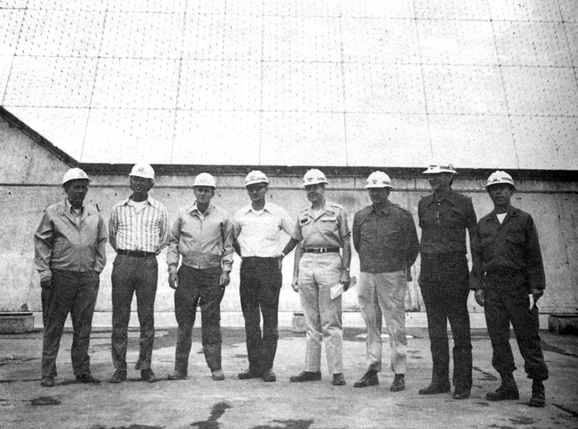
Transfer of the first of the major tactical buildings, the PARB, from control of the Huntsville Division to the Safeguard System Command on August 21, 1972. Source (2).
From left to right: S.N. Purinton, PAR Project Manager, M-KA; G.W. Gilfillan, Division Manager, Missile and Space Division, M-KA; A.D. (Doc) Poteat, Resident Manager, M-KA; Paul C. Steidl, PAR Resident Manager; Colonel Lochlin W. Caffey, Contracting Officer and Deputy Division Engineer, Huntsville; Brigadier General Bates C. Burnell, Huntsville Division Engineer; Barney L. Trawicky, Chief, Construction Division, Huntsville; and Colonel John L. Lillibridge, Grand Forks Area Engineer.
(397 x 295 = 049k) Show | Omit descr (002928) (815 x 605 = 141k) Show | Omit descr
C16 :
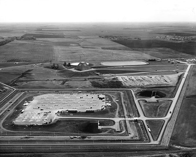
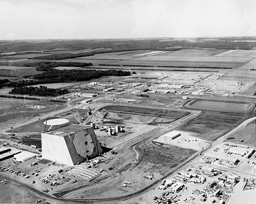
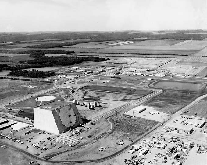
Major construction is complete in this Fall 1972 view of the PAR site. Source (1).
The support structure for the antenna element installation cabs is on the ground at the left front corner of the PAR building.
(371 x 295 = 53k) Show | Omit descr (002904) (679 x 540 = 78k) Show | Omit descr
C17 :
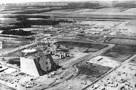
Photo C16 with major facilities labelled. Source (2).
(444 x 295 = 070k) Show | Omit descr (002916) (912 x 606 = 214k) Show | Omit descr
C18 :
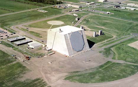
Site cleanup in progress. Source (5).
The Nike Hercules target tracking radar is installed on the roof of the PAR building, with the radar vans on the ground near the left rear of the PARB. This radar was used to help align the phased array radar.
Two temporary antenna towers are also installed in front of the PAR antenna wall (one on the left, one on the right). They were also probably used during initial installation, alignment, and testing of the phased array radar.
The temporary office buildings and parking lot to the left of the PAR building were for the installation and test team. These buildings were removed after activation.
(467 x 295 = 032k) Show | Omit descr (003102) (966 x 596 = 160k) Show | Omit descr